
Fine finish polishing tool

A technology for grinding tools and grinding parts. It is applied in the direction of manufacturing tools, metal processing equipment, abrasives, etc. It can solve the problems of unfavorable control of grinding fluid and flow temperature, cumbersome processing of panel glass, and reduced processing success rate, so as to improve grinding. Efficiency, increase the success rate, improve the effect of processing efficiency

Pending Publication Date: 2018-11-27
CONPROFE TECH GRP CO LTD +1
View PDF0 Cites 4 Cited by
  • Summary
  • Abstract
  • Description
  • Claims
  • Application Information

AI Technical Summary

Problems solved by technology

This makes the current panel glass processing very cumbersome and inefficient.
[0003] At the same time, in the process of the above-mentioned panel logic processing, a variety of grinding wheels are usually used to grind different parts, which makes it necessary to constantly replace different grinding wheels during the processing, thereby reducing the processing time. efficiency
On the other hand, the currently used panel glass processing tools are usually cylindrical and flat, and the processing tools of this shape usually have the characteristics of full coverage, which is not conducive to the control of the polishing fluid, flow and temperature during the polishing process, thereby reducing the The success rate of processing

Method used


Image

  • Fine finish polishing tool
  • Fine finish polishing tool
  • Fine finish polishing tool

Examples


Embodiment 1

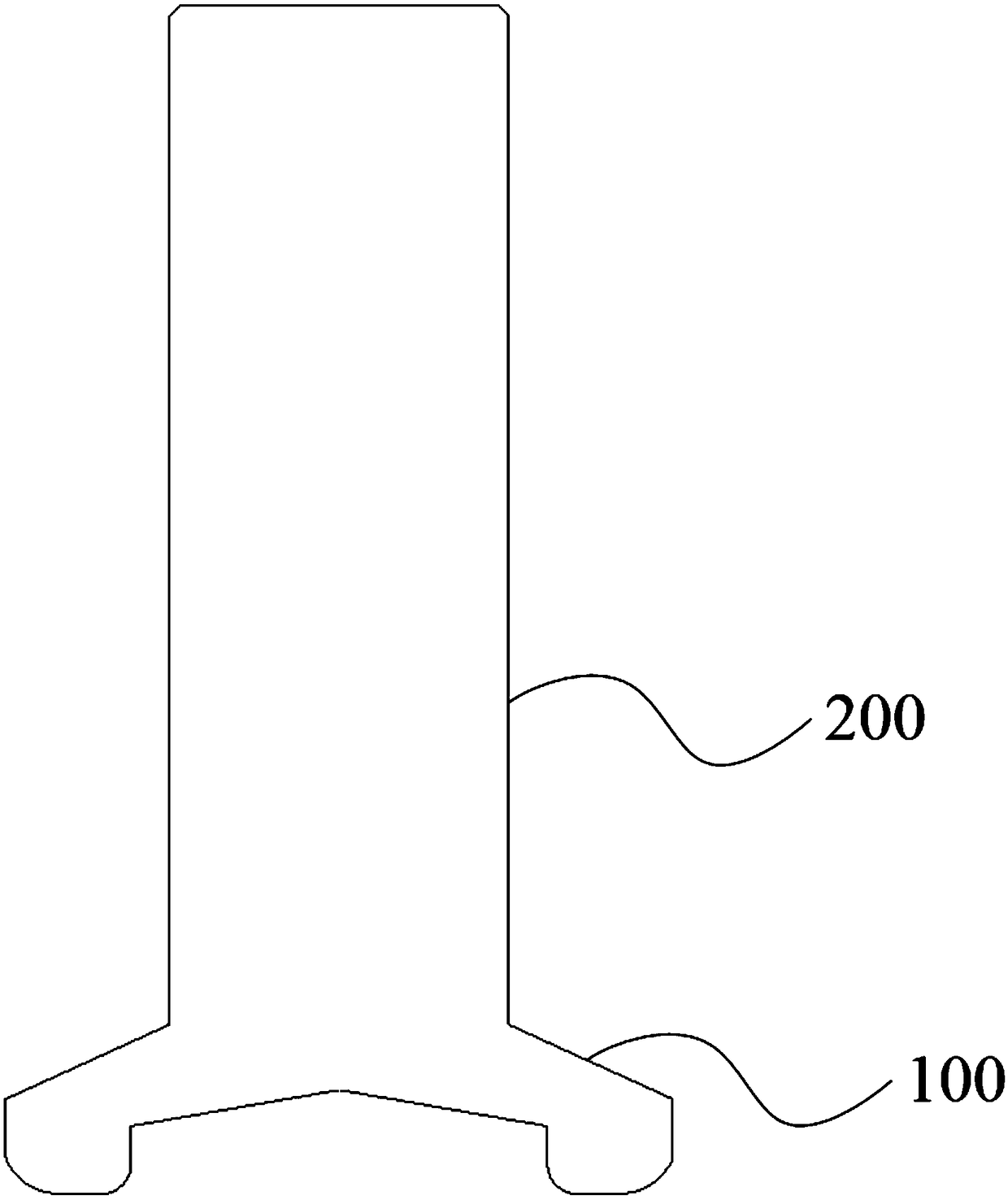
[0057] see figure 1 , figure 1 It is a schematic cross-sectional structure diagram of a finishing grinding tool provided in this embodiment.

[0058] Such as figure 1 As shown, this finishing grinding tool includes a grinding main body 100 and an installation connecting rod 200, wherein,

[0059] The installation connecting rod 200 is cylindrical, the grinding main body 100 is disc-shaped, the installation connecting rod 200 is coaxially connected with the grinding main body 100, and the ratio of the diameter of the grinding main body 100 to the diameter of the installation connecting rod 200 is 1.2-2.4;

[0060] The grinding body 100 includes a connecting portion 120 and a grinding portion 110;

[0061] The shape of the connecting portion 120 is a truncated cone, with a circular top surface and a bottom surface, and a side surface shaped as a conical surface; the diameter of the top surface is smaller than the diameter of the bottom surface; the top surface is connected co...

Embodiment 2

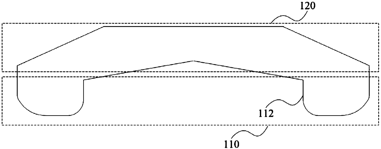
[0085] see figure 2 , figure 2 yes figure 1 A partial sectional structural schematic diagram of a sectional structural schematic diagram of a finishing grinding tool is provided.

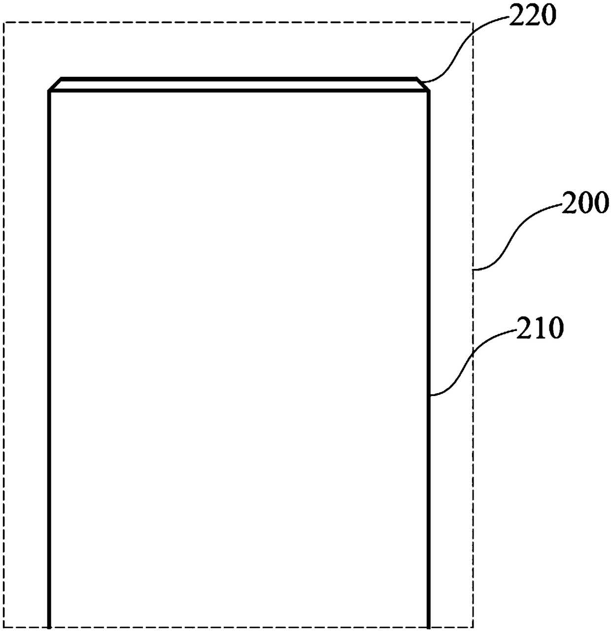
[0086] see image 3 , image 3 yes figure 1 A partial sectional structural schematic diagram of a sectional structural schematic diagram of a finishing grinding tool is provided.

[0087] Such as figure 2 and image 3 As shown, in the grinding main body 100, the discharge groove 111 is in the shape of a prism;

[0088] The taper angle of the connecting portion 120 is 145° to 170°.

[0089] In this embodiment, the bottom surface of the grinding main body 100 can be a conical surface, which can provide an internal space for grinding and is convenient for shaping; meanwhile, the inner surface of the conical surface can also provide ventilation and heat dissipation for grinding, and limit the splashing of grinding powder etc.

[0090] In this embodiment, the angle of the side of the round t...

Embodiment 3

[0118] On the basis of Embodiment 1 or Embodiment 2, in the finishing grinding tool, the axial length of the connecting part 120, the axial length of the grinding part 110 and the axial length of the connecting rod 200 satisfy the following relationship:

[0119] a*L=X+Y;

[0120] Among them, a is a preset constant coefficient, the size is 0.15 ~ 0.25;

[0121] L is the axial length of the connecting rod 200;

[0122] X is the axial length of the connecting portion 120;

[0123] Y is the axial length of the grinding part 110 .

[0124] As an optional implementation manner, the axial length of the connecting portion 120 and the axial length of the grinding portion 110 satisfy the following relationship:

[0125] Y=b*X;

[0126] Among them, b is a preset constant coefficient, the size is 0.15 ~ 0.25.

[0127] As an optional embodiment, the peripheral arc length of the discharge groove 111 and the peripheral arc length of the grinding section 112 satisfy the following relati...


PUM


Abstract

The invention provides a fine finish polishing tool. The fine finish polishing tool comprises a grinding body and an installing connecting rod. The installing connecting rod is cylindrical, and the grinding body is disc-shaped. The installing connecting rod is coaxially connected with the grinding body, and a specific value of a diameter of the grinding body and a diameter of the installing connecting rod is 1.2-2.4. The grinding body comprises a connecting part and a polishing part. The connecting part is truncated cone-shaped, and has circular top face and bottom face, and a side face of which a shape is a circular conical surface. A diameter of the top face is less than a diameter of the bottom face. The top face is coaxially connected with the installing connecting rod. The polishing part is formed on the bottom face. The polishing part is annular and protruded and installed at the peripheral part of the bottom face of the connecting part, and the polishing part is provided with multiple discharging channels for discharging wastes generated in a polishing process. It can be clearly shown that the described fine finish polishing tool is capable of meeting multiple polishing requirements through a high-precision small-scale design, improving processing efficiency, and improving a processing success rate.

Description

technical field [0001] The invention relates to the field of mechanical processing, in particular to a finishing grinding tool. Background technique [0002] At present, in the process of panel glass processing, it is usually necessary to use a variety of tools including glass brushes, grinding wheels, polishing machines, etc. to process the panel glass. Do refinement. This just makes the processing process of current panel glass very loaded down with trivial details, and efficiency is low. [0003] At the same time, in the process of the above-mentioned panel logic processing, a variety of grinding wheels are usually used to grind different parts, which makes it necessary to constantly replace different grinding wheels during the processing, thereby reducing the processing time. efficiency. On the other hand, the currently used panel glass processing tools are usually cylindrical and flat, and the processing tools of this shape usually have the characteristics of full co...

Claims


Application Information

Patent Timeline
Patent Type & Authority Applications(China)
IPC IPC(8): B24D7/14
CPCB24D7/14
Inventor 颜炳姜李伟秋林一松
Owner CONPROFE TECH GRP CO LTD
Learn More