Road cutting machine for road construction

A cutting machine and road technology, applied in the field of road equipment, can solve the problems of inability to adjust the depth, easy to slip the rotation of the cutting blade, increase the workload, etc., to improve convenience and stability, ensure safety and high efficiency, and cut a wide range Effect

Active Publication Date: 2020-09-25
广东恒大路桥建设有限公司
View PDF9 Cites 0 Cited by
  • Summary
  • Abstract
  • Description
  • Claims
  • Application Information

AI Technical Summary

Problems solved by technology

[0003] However, the existing road cutting machines still have some deficiencies in actual use. For example, when cutting, they lack the necessary guiding structure, and due to the relatively high hardness of the road surface, the cutting machine is easy to cause the cutting piece to break after it is offset and misplaced. damage, poor stability in use, and the existing cutting machine structure is inconvenient to adjust the height of the cutting piece, and the depth cannot be adjusted for different road surface structures, which may easily cause cutting not in place, or the cutting depth is too large to increase the workload. The effect is not ideal, and the tension of the transmission cannot be guaranteed when driving at the same time, it is easy to slip and cause the cutting piece to rotate unsteadily, and the cutting effect is not ideal

Method used


Image

  • Road cutting machine for road construction
  • Road cutting machine for road construction
  • Road cutting machine for road construction

Examples


Embodiment Construction

[0023] The following will clearly and completely describe the technical solutions in the embodiments of the present invention with reference to the accompanying drawings in the embodiments of the present invention. Obviously, the described embodiments are only some, not all, embodiments of the present invention. Based on the embodiments of the present invention, all other embodiments obtained by persons of ordinary skill in the art without making creative efforts belong to the protection scope of the present invention.

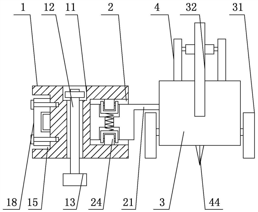
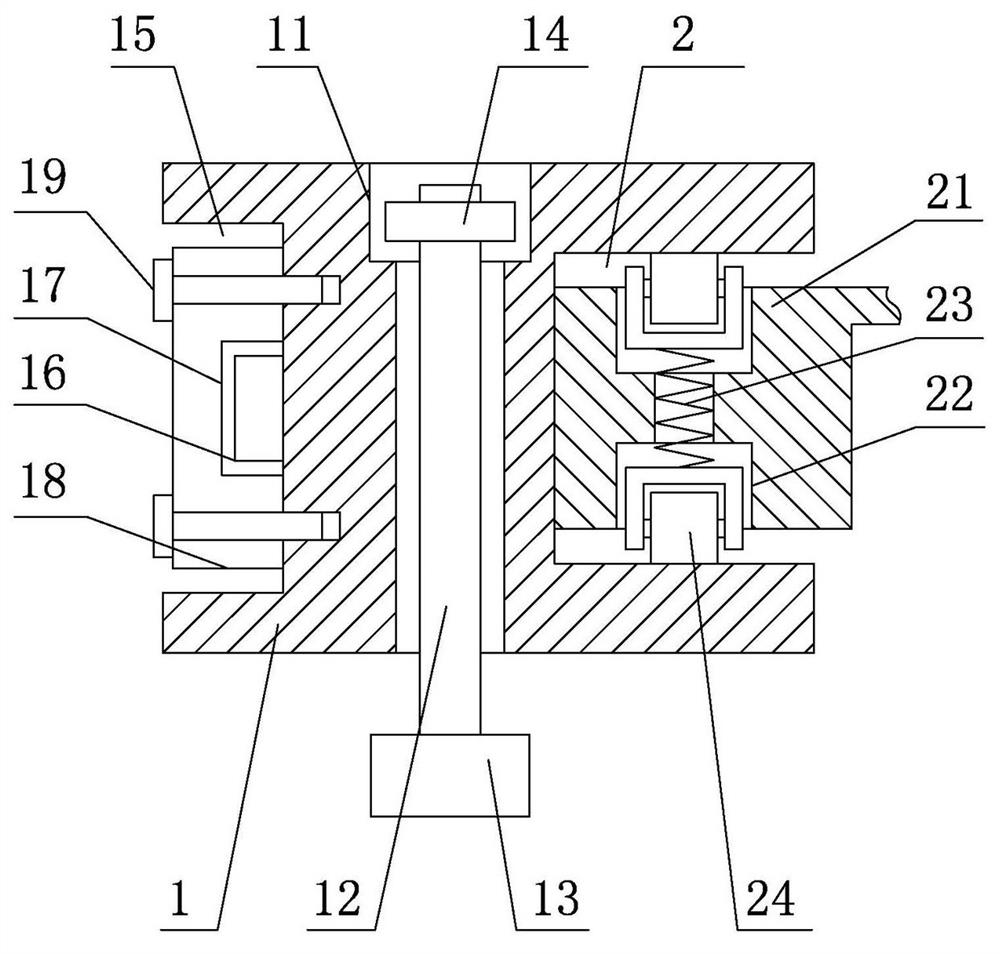
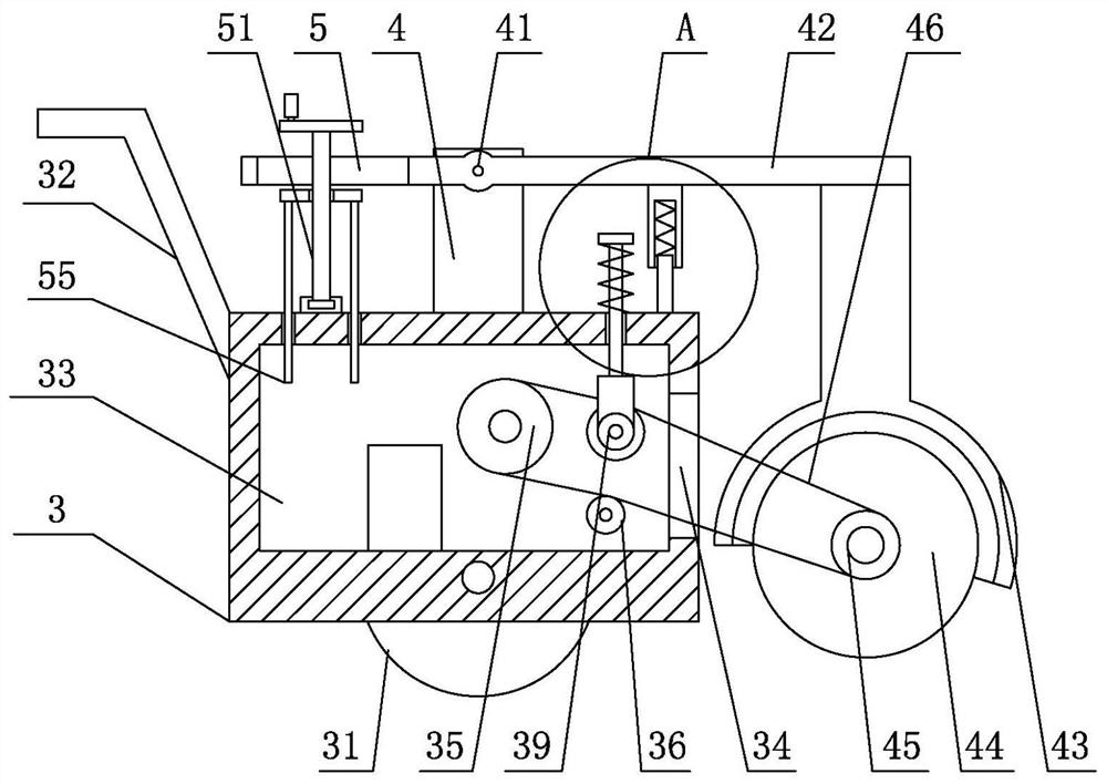
[0024] see Figure 1-5 , the present invention provides a technical solution: a road surface cutting machine for road construction, including a guide plate 1, the inner two ends of the guide plate 1 are provided with connecting holes 11, the inner surface of the connecting hole 11 is slidingly connected with a fixing bolt 12, The lower surface of the fixing bolt 12 is provided with a positioning head 13, and the outer upper end of the fixing bolt 12 is threade...


PUM


Abstract

The invention discloses a road surface cutting machine for road construction. The cutting machine comprises a guiding plate, connecting holes are formed in the two ends in the guiding plate, and a fixing bolts is slidably connected to the surfaces on the inner sides of the connecting holes; a locating head is arranged on the lower surface of the fixing bolt, a compressing nut is in threaded connection to the upper end of the outer surface of the fixing bolt, and a connecting groove is formed in the surface of the front end of the guiding plate; a locating block is arranged on the bottom surface in the connecting groove, a connecting plate is slidably connected to the outer surface of the locating block through a locating groove, the outer surface of the connecting plate is slidably connected to the surface on the inner side of the connecting groove, and the surfaces on the two sides of the connecting plate are fixedly installed on the surface on the inner side of the connecting groovethrough connecting screws. According to the road surface cutting machine for road construction, the guiding plate structure with a guiding groove is combined with the guiding block to make contact with a rack, therefore the convenience and stability of the using are greatly improved, and the safe and efficient maintenance of highways are ensured.

Description

technical field [0001] The invention relates to the technical field of road equipment, in particular to a road surface cutting machine for road construction. Background technique [0002] In the current road maintenance process, it is necessary to cut off the damaged local road surface, and then fill and repair it. This requires the use of a road surface cutting machine to operate. The gasoline engine drives the cutting blade to cut, which can effectively remove the damaged road surface structure. [0003] However, the existing road cutting machines still have some deficiencies in actual use. For example, when cutting, they lack the necessary guiding structure, and due to the relatively high hardness of the road surface, the cutting machine is easy to cause the cutting piece to break after it is offset and misplaced. damage, poor stability in use, and the existing cutting machine structure is inconvenient to adjust the height of the cutting piece, and the depth cannot be adj...

Claims


Application Information

Patent Timeline
Patent Type & Authority Patents(China)
IPC IPC(8): E01C23/09
CPCE01C23/094
Inventor 不公告发明人
Owner 广东恒大路桥建设有限公司
Why Eureka
Try Eureka