Mounting structure for lift type security monitoring equipment carrier cart

A technology of installation structure and security monitoring, applied in the direction of mechanical equipment, supporting machine, machine/stand, etc., can solve the problems of high airflow speed, shaking of the installation structure, inability to automatically descend, etc., to avoid unnecessary work, avoid angle offset effect

Inactive Publication Date: 2018-11-27
沈金章
View PDF0 Cites 1 Cited by
  • Summary
  • Abstract
  • Description
  • Claims
  • Application Information

AI Technical Summary

Problems solved by technology

[0003] 1. The security monitoring equipment is located in a relatively high place, and the air velocity in the high altitude is relatively large, which easily causes the installation structure to shake, resulting in an angle deviation of the security monitoring equipment, so that the security monitoring equipment cannot achieve better monitoring , it is also necessary to lower the security monitoring equipment for angle adjustment and maintenance, which increases the workload
[0004] 2. The installation structure of the general lift-type security monitoring equipment carrying trolley uses ropes to raise the security monitoring equipment to a high place for work. When encountering a strong wind level, the installation structure will be lowered if the rope does not shake well, and it cannot automatically Descending, causing security monitoring equipment to be damaged by the typhoon at a high place

Method used


Image

  • Mounting structure for lift type security monitoring equipment carrier cart
  • Mounting structure for lift type security monitoring equipment carrier cart
  • Mounting structure for lift type security monitoring equipment carrier cart

Examples


Embodiment

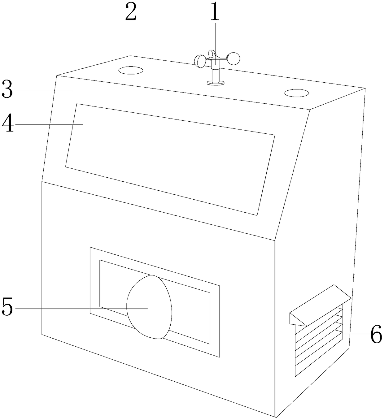
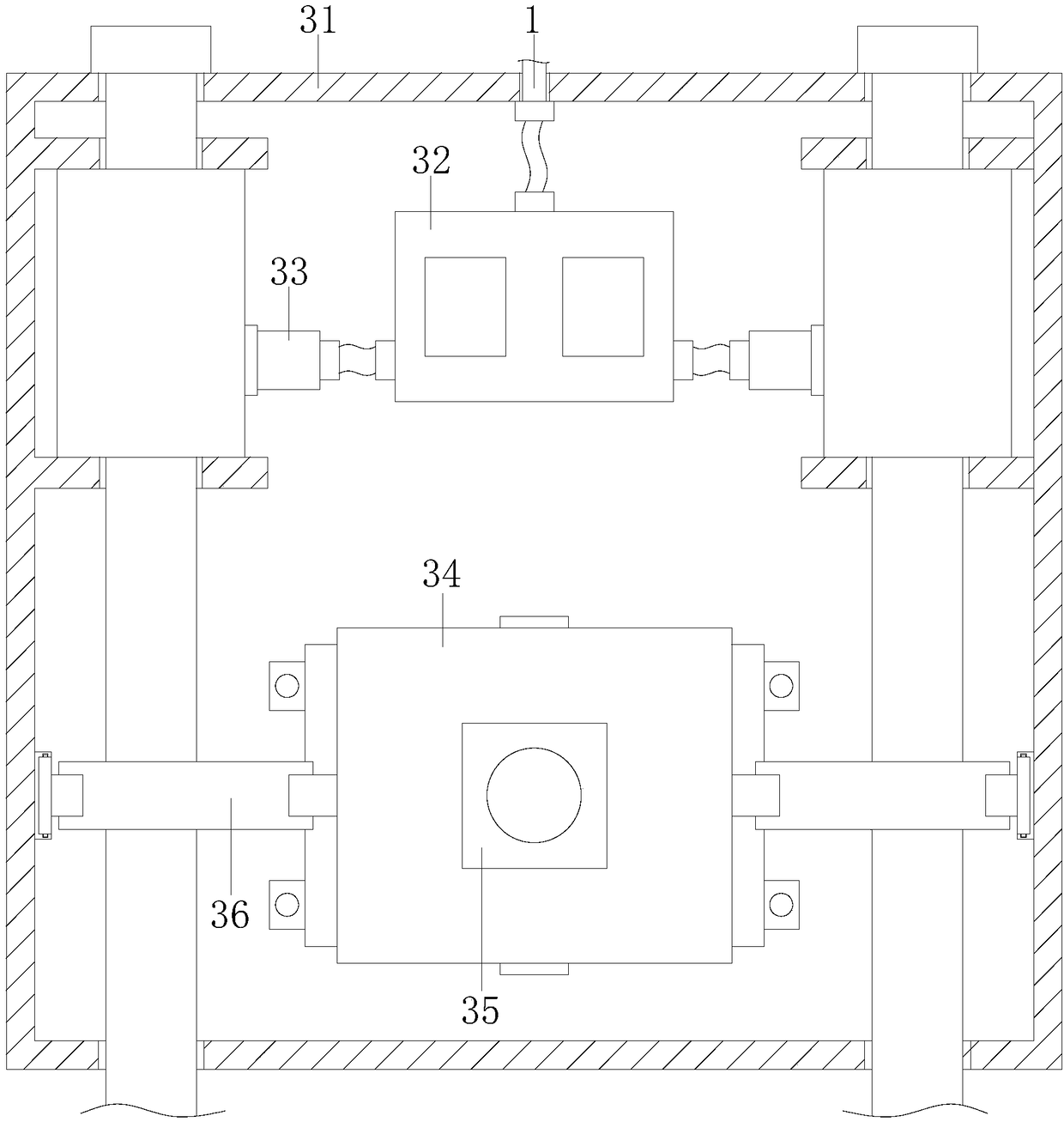
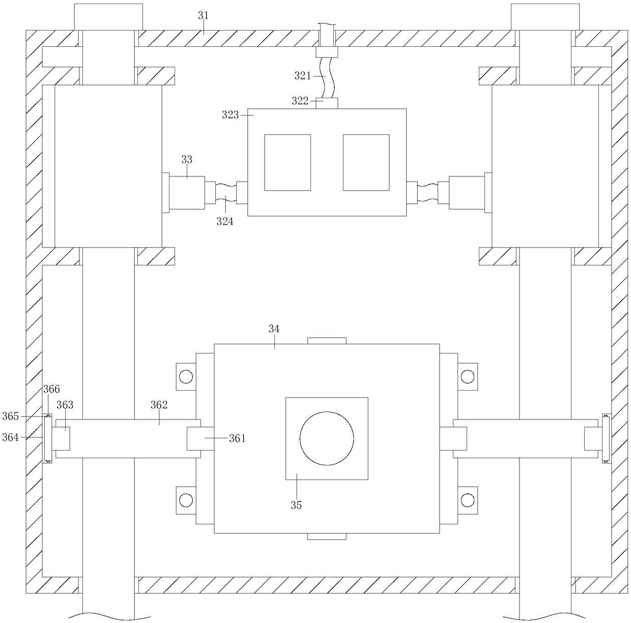
[0028] see Figure 1-Figure 6 , the present invention provides an installation structure for carrying a trolley with lifting security monitoring equipment. At the top of the structure 3, the lifting hole 2 is embedded in the installation structure 3, the front surface of the top of the installation structure 3 is provided with a window 4, the bottom of the installation structure 3 is embedded with a camera 5 and is electrically connected by a wire, the heat dissipation hole 6 is embedded on the outer surface of the installation structure 3, and the installation structure 3 includes a housing 31, a control mechanism 32, a lifting mechanism 33, a stabilization mechanism 34, a camera mount 35, and a fixing mechanism 36.

[0029] The wind speed sensor 1 is vertically installed on the top of the casing 31, and the top inside of the casing 31 is provided with a control mechanism 32, the control mechanism 32 is electrically connected with the wind speed sensor 1 through a wire, and t...


PUM


Abstract

The invention discloses a mounting structure for a lift type security monitoring equipment carrier cart. The mounting structure comprises an air velocity sensor, a lift hole, a mounting structure, a window, a camera and a radiating hole. The air velocity sensor is vertically mounted at the top end of the mounting structure; the lift hole is embedded in the mounting structure; the window is arranged on the front surface of the top end of the mounting structure; the camera is embedded at the bottom end of the mounting structure and is in electric connection with the same through a conductor wire; and the radiating hole is embedded in the outer surface of the mounting structure. The mounting structure comprises a shell, a control mechanism, a lift mechanism, a stabilizing mechanism and a camera holder; the camera and the mounting structure are kept at a stable state through action of an outer ring stabilizing mechanism and an inner ring stabilizing mechanism inside the stabilizing mechanism, influence from air flow at high level is avoided, normal operation of the camera is guaranteed, and the operation of dropping the camera to repair is avoided; besides, in a typhoon day, the control mechanism controls the lift mechanism automatically to fall, the gravity of the mounting structure is lowered, and the mounting structure is protected against typhoon.

Description

technical field [0001] The invention relates to the field of installation structures for carrying trolleys with elevating security monitoring equipment, in particular to an installation structure for carrying trolleys with elevating security monitoring equipment. Background technique [0002] In order to make the monitoring field of view better, the security monitoring equipment is raised to a certain height. The installation structure of the security monitoring equipment carrying trolley has the following disadvantages: [0003] 1. The security monitoring equipment is located in a relatively high place, and the air velocity in the high altitude is relatively large, which may easily cause the installation structure to shake, resulting in an angle deviation of the security monitoring equipment, so that the security monitoring equipment cannot achieve better monitoring , It is also necessary to lower the security monitoring equipment for angle adjustment and maintenance, whic...

Claims


Application Information

Patent Timeline
IPC IPC(8): F16M11/04F16M11/24
CPCF16M11/04F16M11/24
Inventor 沈金章
Owner 沈金章
Why Eureka
Try Eureka