
Flame stabilization device, combustion device and test method

A flame stabilization and combustion device technology, which is applied in the field of combustion devices and flame stabilization devices, can solve the problems of reduced flame stability performance, increased resistance, and inability to adjust, and achieves the effects of low cost, good performance, and simple structure

Pending Publication Date: 2018-11-27
HUNAN AIRTOPS INTELLIGENT TECH CO LTD
View PDF7 Cites 0 Cited by
  • Summary
  • Abstract
  • Description
  • Claims
  • Application Information

AI Technical Summary

Problems solved by technology

At present, in the research on the influence of the L / D value of the concave cavity on the combustion performance, the method of randomly selecting discrete points is mostly used. The typical fixed discrete values ​​selected are limited to parameters such as 3, 5, 7, and 9, and cannot be adjusted.
During the test, the concave cavity flame stabilizer cannot be adjusted according to the change of the airflow conditions before and after ignition and before and after the working condition, so that the flame stability performance is reduced or the resistance is increased under non-design working conditions, and the optimal performance of the concave cavity flame stabilizer cannot be exerted. performance

Method used


Image

  • Flame stabilization device, combustion device and test method
  • Flame stabilization device, combustion device and test method
  • Flame stabilization device, combustion device and test method

Examples


Embodiment 1

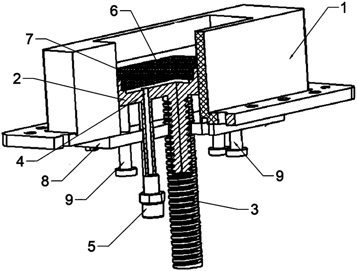
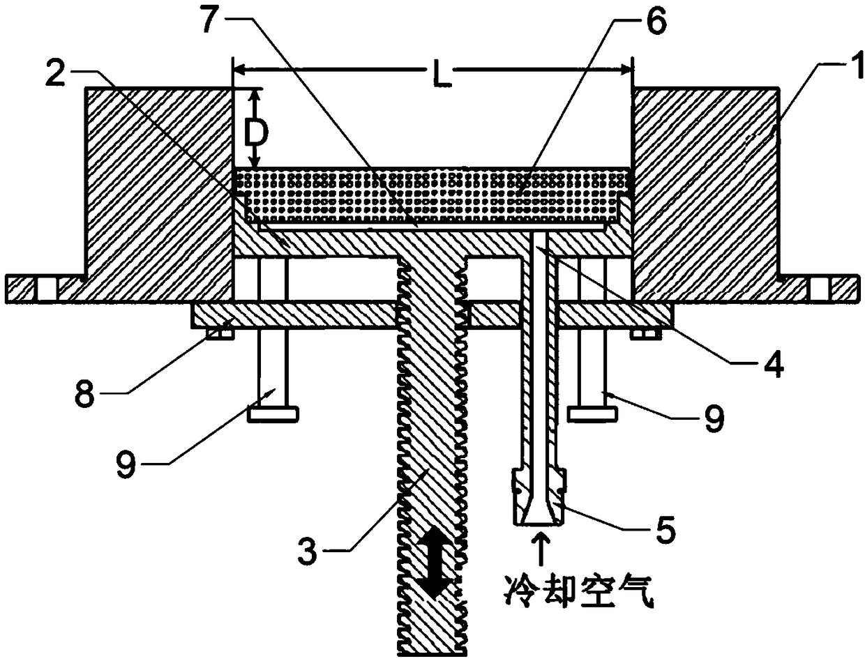
[0035] Such as figure 1 As shown, the flame stabilizing device of the present embodiment includes a base, a sliding plate and a translation transmission rod; the base has a recessed cavity; the sliding plate is arranged in the cavity, and can move along the axis of the cavity in the cavity. to move; the translation transmission rod is fixedly installed on the bottom surface of the slide plate. In this embodiment, the translation transmission rod is a worm. Driven by a driver such as a driving motor, the sliding plate can be pushed to slide in translation along the axial direction of the cavity in the cavity. It should be noted, figure 1 It is a partial sectional view of the flame stabilizer with one corner cut away. Such as figure 2 As shown in , L represents the length of the cavity, and D represents the depth of the cavity. By sliding the sliding plate up and down in the cavity, the depth of the cavity can be continuously adjusted, so that the length-depth ratio of the...

Embodiment 2

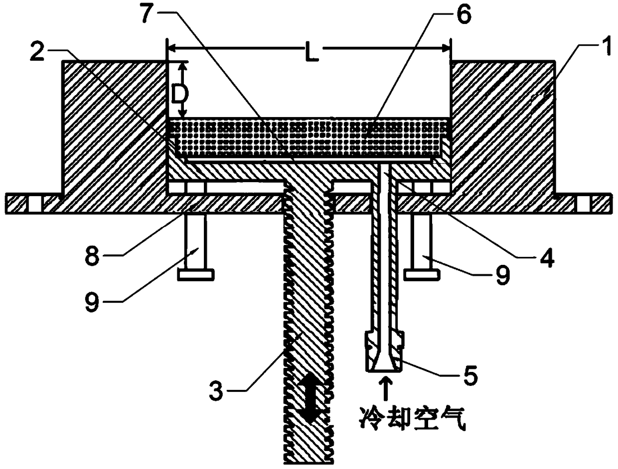
[0044] The flame stabilizing device of this embodiment is basically the same as that of Embodiment 1, the difference is that no bottom plate and positioning rod are provided, but a limiting block, a first positioning body, a second positioning body and a limiting body that cooperate with the first positioning body are added. Technical features such as bit bars.

[0045] Specifically, such as Figure 4 and Figure 5 As shown, the flame stabilizing device of the present embodiment includes a base, a sliding plate and a translation transmission rod; the base has a recessed cavity; the sliding plate is arranged in the cavity, and can move along the axis of the cavity in the cavity. to move; the translation transmission rod is fixedly installed on the bottom surface of the slide plate. In this embodiment, the translation transmission rod is a worm. Driven by a driver such as a driving motor, the sliding plate can be pushed to slide in translation along the axial direction of the...


PUM


Abstract

The invention discloses a flame stabilization device, a combustion device and a test method, and the flame stabilization device comprises a base, a sliding plate and a translation transmission rod; aconcave cavity is formed in the base; the sliding plate is arranged in the cavity and can move in the axial direction of the cavity in the cavity; the translation transmission rod is fixedly mounted on the bottom surface of the sliding plate. The flame stabilization device, the combustion device and the test method have the advantages that the structure is simple, continuous adjustment and reciprocating adjustment of the depth of the concave cavity can be realized, the diversified test requirements can be met, and the efficiency is higher.

Description

technical field [0001] The invention relates to the technical field of scramjet flame stabilization and its test, in particular to a flame stabilization device, a combustion device and a test method. Background technique [0002] The speed of supersonic combustion is fast, and the residence time of fuel in the combustion chamber is only milliseconds. It is necessary to complete the mixing of fuel and incoming flow, ignite, form a diffusion flame and spread to the entire combustion chamber in such a short time to achieve stable and efficient combustion. The burning flow field is very difficult. The flow velocity in the combustion chamber of the scramjet engine reaches more than 500m / s, and it changes with the change of the equivalence ratio, which puts forward higher requirements for the stable flame range and working stability of the flame stabilizer. How to design a flame stabilizer with high combustion efficiency, wide stable flame boundary, low resistance and low loss ha...

Claims


Application Information

Patent Timeline
Patent Type & Authority Applications(China)
IPC IPC(8): F23R3/22G01M99/00
CPCF23R3/22G01M99/00
Inventor 罗世彬
Owner HUNAN AIRTOPS INTELLIGENT TECH CO LTD
Learn More