

Evaporator heat exchange device and integral air energy water heater
A technology of heat exchange device and evaporator, which is applied in the direction of evaporator/condenser, fluid heater, lighting and heating equipment, etc. It can solve the problems of poor heat transfer performance on the evaporation side and low heating capacity of the compressor
- Summary
- Abstract
- Description
- Claims
- Application Information
AI Technical Summary
Problems solved by technology
Method used
Image

Examples
Embodiment Construction
[0018] The present invention will be further described below in conjunction with the embodiments and the accompanying drawings.
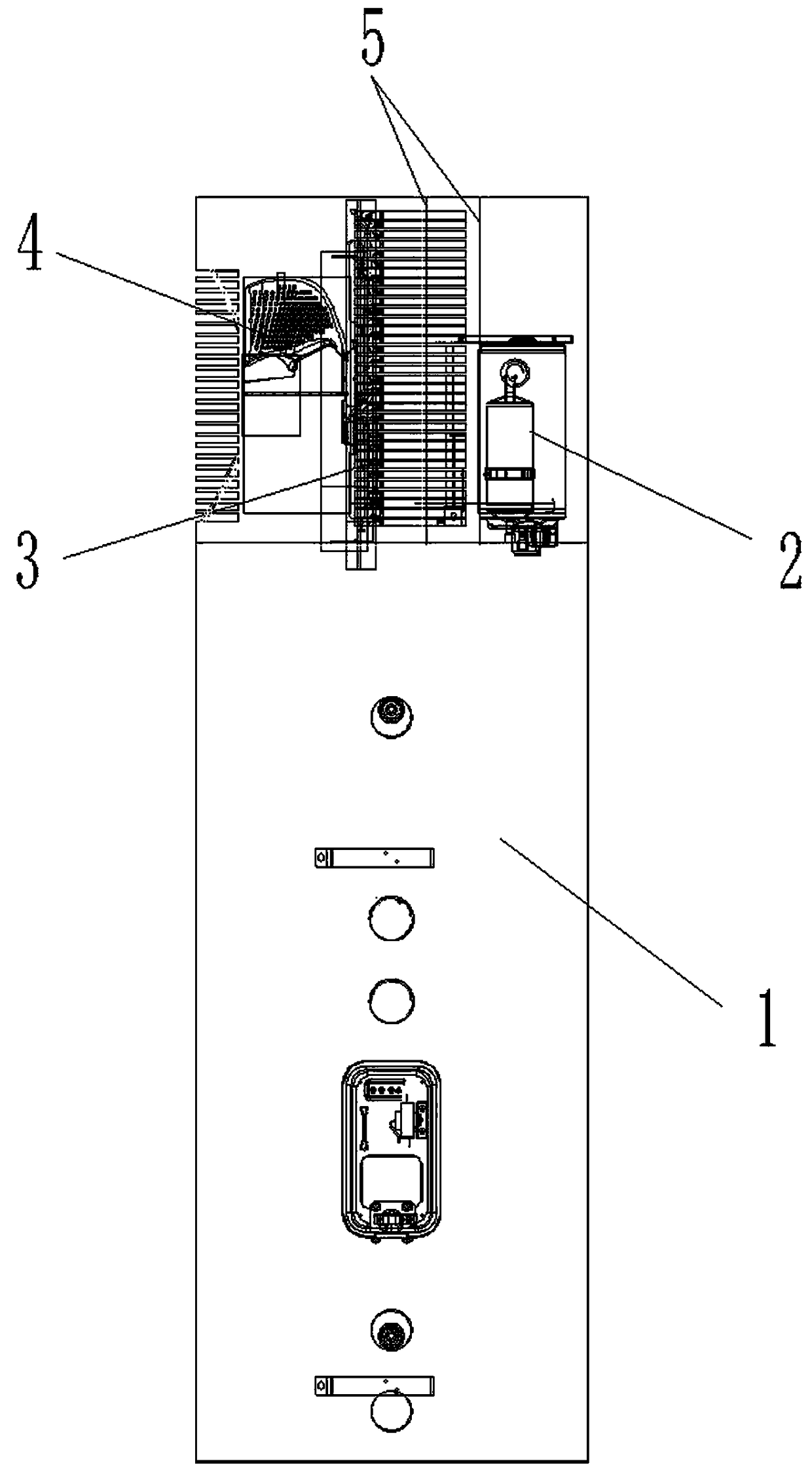
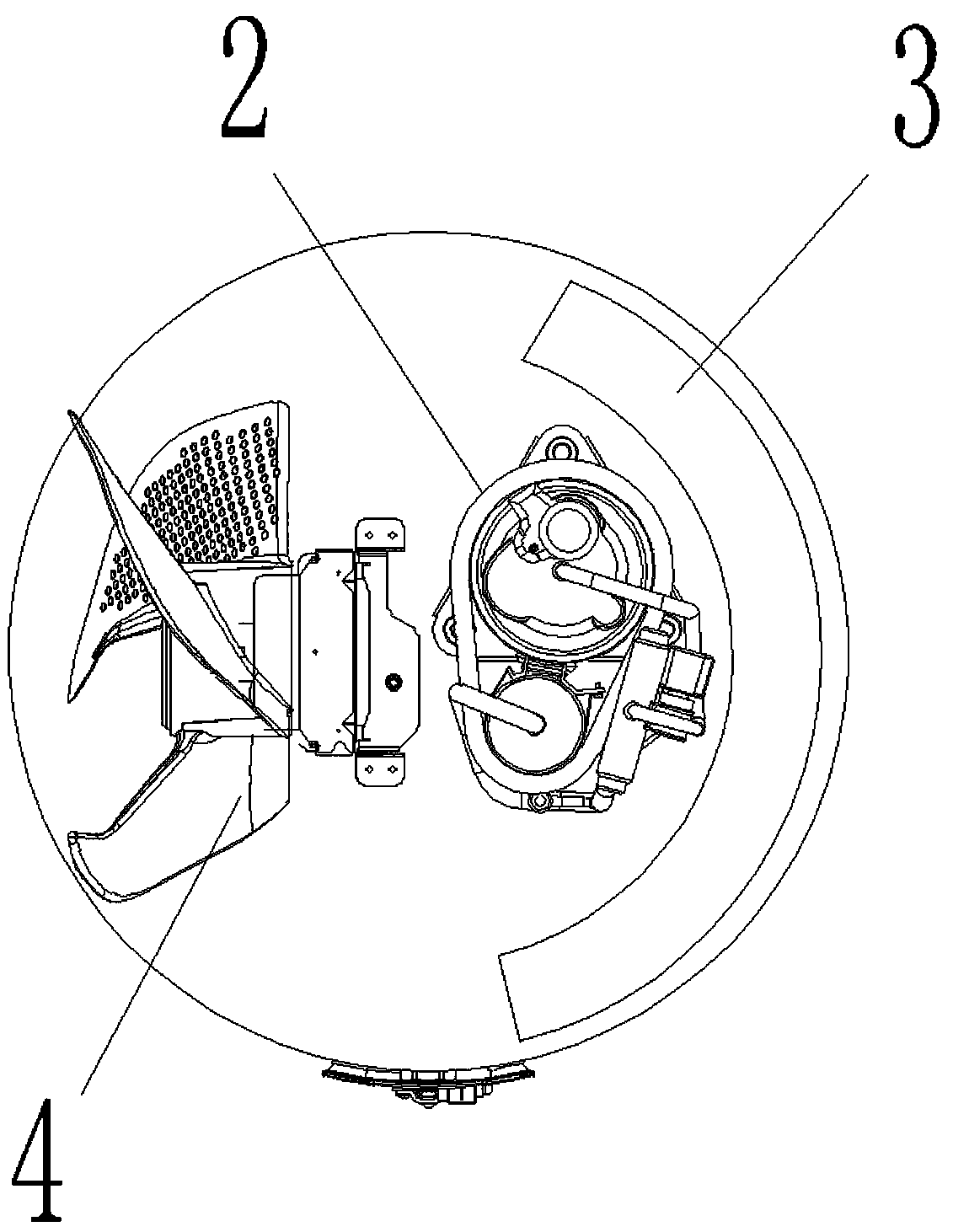
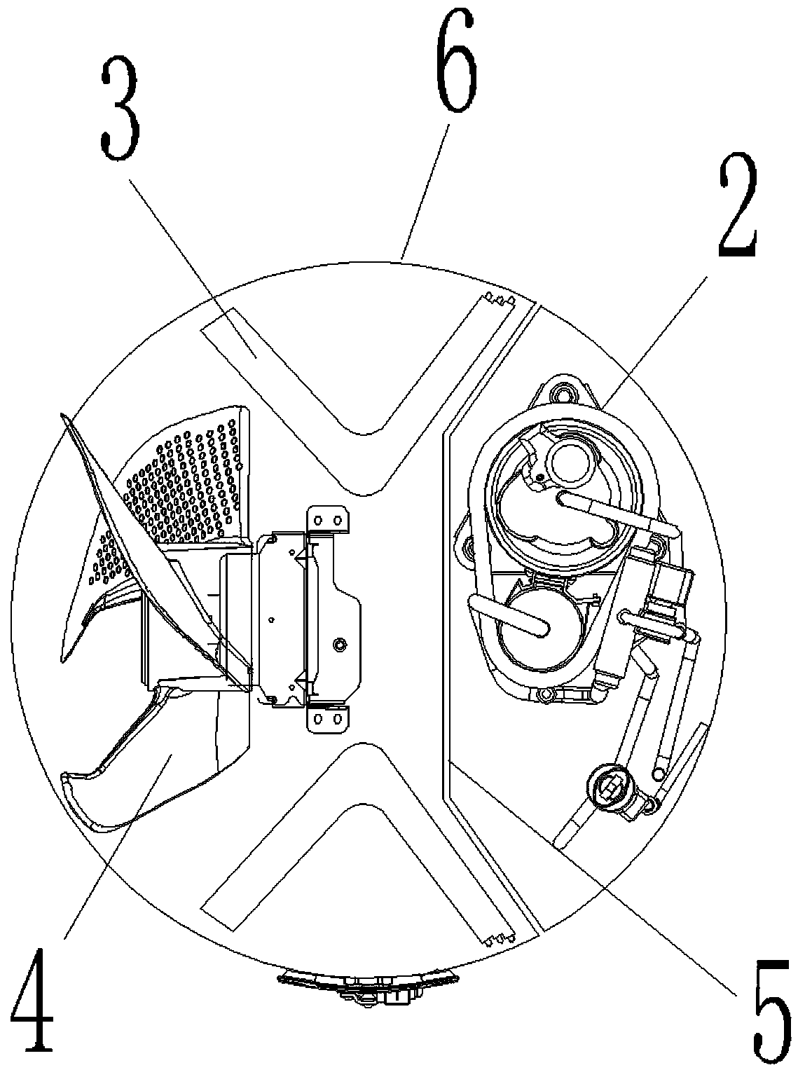
[0019] like figure 1 , image 3 , Figure 4 , Figure 5 Shown is the integrated air energy water heater proposed by the present invention and three kinds of evaporator heat exchange devices with different structures. The evaporator heat exchange device includes: an axial flow fan 4 , an evaporator 3 , and a compressor 2 . The evaporator 3 can be designed in different structural shapes, and placed in a cavity opposite to the axial flow fan 4 and the compressor 2 , and the compressor 2 is located in a closed space separating it from the evaporator 3 . And the enclosed space is formed by the arc partition plate 5 and the casing 6 arranged between the compressor 2 and the evaporator 3 . According to needs, the evaporator can be a V-shaped structure, and a pair is arranged symmetrically; the evaporator can also be an integral bent structure; the eva...
PUM
 Abstract
Description
Claims
Application Information