
Disease automatic detection system for bridge chamber

An automatic detection and bridge box technology, applied in the field of diseases, can solve the problems of lack of coverage, low accuracy, waste of resources, etc., to avoid changes in objectivity, improve work accuracy, and easy to use equipment.

Pending Publication Date: 2018-11-27
赵启林 +1
View PDF0 Cites 3 Cited by
  • Summary
  • Abstract
  • Description
  • Claims
  • Application Information

AI Technical Summary

Problems solved by technology

[0002] At present, in the actual inspection of the structure in the box room, different types of equipment are required to inspect the structure for the inspection of the appearance of the bridge structure and the tracking and monitoring of the disease, which greatly affects the efficiency of the inspection work. At the same time, manual inspection in the dark box room environment The accuracy and safety of the
At present, the long-term observation of bridge cracks is generally recorded during the routine inspection compared with the previous inspection, so that the crack development and deformation process cannot be accurately obtained. At present, the long-term observation of cracks is generally installed with separate monitoring equipment, and the entire inspection process requires A large amount of manual intervention not only wastes resources, but also requires high costs and lack of coverage
[0003] In the past, the commonly used detection method was based on artificial vision for on-site investigation and detection of diseases, but it could not well meet the requirements of the bridge chamber. Completing the survey of a section of highway requires a considerable amount of manpower or takes a long time for inspection; the accuracy is low, and it is greatly affected by the environment and inspectors. would interfere with the assessment of pavement damage

Method used


Image

  • Disease automatic detection system for bridge chamber

Examples


Embodiment Construction

[0034] In order to better understand the technical content of the present invention, specific embodiments are given together with the attached drawings for description as follows.

[0035] Aspects of the invention are described in this disclosure with reference to the accompanying drawings, which show a number of illustrated embodiments. Embodiments of the present disclosure are not necessarily intended to include all aspects of the invention. It should be appreciated that the various concepts and embodiments described above, as well as those described in more detail below, can be implemented in any of numerous ways, since the concepts and embodiments disclosed herein are not limited to any implementation. In addition, some aspects of the present disclosure may be used alone or in any suitable combination with other aspects of the present disclosure.

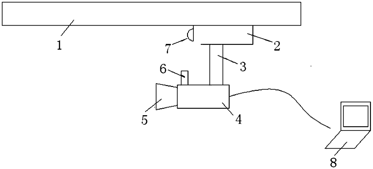
[0036] Such as figure 1 As shown, an automatic detection system for indoor diseases of a bridge box, the automatic detectio...


PUM


Abstract

The invention provides a disease automatic detection system for a bridge chamber. The automatic detection system comprises a travelling track, an illuminating system, a lifting cloud deck and a camera, wherein the travelling track is arranged in the bridge chamber for supporting a moving device; the moving device is movably arranged on the track; the illuminating system is arranged at the front end of the moving device for providing illumination for the automatic detection system; the camera is arranged on the lifting cloud deck and is connected to a management computer to call an automatic focusing lens to shoot an image of an appointed area according to a control command of the management computer and sends the shot image to the management computer; a prism-free laser range finder is arranged on one side of the camera; and the management computer responding to the image sent by the camera transfers a disease automatic recognizing and image recognizing computer program to recognize diseases in the image. The equipment is easy to use and operate, and the workload of appearance inspection is reduced greatly.

Description

technical field [0001] The invention relates to the field of diseases, in particular to an automatic detection system for diseases in a bridge box room. Background technique [0002] At present, in the actual inspection of the structure in the box room, different types of equipment are required to inspect the structure for the inspection of the appearance of the bridge structure and the tracking and monitoring of the disease, which greatly affects the efficiency of the inspection work. At the same time, manual inspection in the dark box room environment The accuracy and security are not guaranteed. At present, the long-term observation of bridge cracks is generally recorded during the routine inspection compared with the previous inspection, so that the crack development and deformation process cannot be accurately obtained. At present, the long-term observation of cracks is generally installed with separate monitoring equipment, and the entire inspection process requires A...

Claims


Application Information

Patent Timeline
Patent Type & Authority Applications(China)
IPC IPC(8): G01N21/88
CPCG01N21/8806G01N21/8851G01N2021/8874G01N2021/8887
Inventor 赵启林周建华朱彬殷海华芮挺周伟周德宝尤启蒙王国军孙呈齐杨凌
Owner 赵启林
Learn More