CAN-bus-based network management method and system

A CAN bus and network management technology, applied in the field of network management, can solve problems such as waste and waste of vehicle battery power, and achieve the effect of reducing unnecessary waste

Active Publication Date: 2018-11-27
ANHUI JIANGHUAI AUTOMOBILE GRP CORP LTD
View PDF7 Cites 16 Cited by
  • Summary
  • Abstract
  • Description
  • Claims
  • Application Information

AI Technical Summary

Problems solved by technology

[0004] It can be seen that the above scheme can realize the dormancy and wake-up of each node in the CAN network, which reduces the power consumption of the vehicle battery to a certain extent. For the rest of the nodes

Method used


Image

  • CAN-bus-based network management method and system
  • CAN-bus-based network management method and system
  • CAN-bus-based network management method and system

Examples


specific Embodiment 1

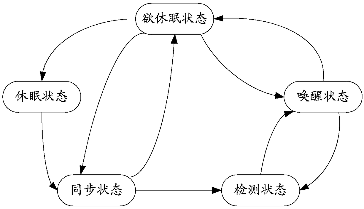
[0111] When the driver powers off the vehicle for defense, the body controller BCM, combination instrument ICM, central navigation MP5 and air conditioning controller HVAC are controlled by the logic of the built-in state conversion machine and enter the sleep state one after another, so that the entire CAN network enters the sleep state At this time, unnecessary waste of on-board battery is avoided, and the whole vehicle enters a low-power operation mode. Suppose that after a period of time, the driver wants to take out an object, such as a backpack, from the vehicle. At this time, the driver unlocks the vehicle and opens the door. This function only involves the body controller BCM, so it only needs to follow the built-in The logic control of the state conversion machine can wake up the body controller BCM. The remaining combination instrument ICM, central navigation MP5 and air conditioning controller HVAC do not meet the preset wake-up conditions, so they continue to stay in...

specific Embodiment 2

[0112] When the driver powers off the vehicle, he presses the HVAC switch of the air conditioner controller to make the air conditioner controller HVAC enter the working state. Because the air conditioner only needs the target node HVAC to be in the awake state, it is based on the built-in The logic control of the state transformation machine in a target node, the remaining body controller BCM, combination instrument ICM and central control navigation MP5 do not need to be in the wake-up state, that is, the remaining body controller BCM, combination instrument ICM and central control navigation MP5 does not need to be in the awake state to be in the dormant state, and when the driver no longer continues to use the air-conditioning air energy and presses the HVAC switch of the air-conditioning controller, the HVAC of the air-conditioning controller enters the dormant state, thereby turning the car battery The power consumption is reduced to a minimum.

[0113] The following descri...


PUM


Abstract

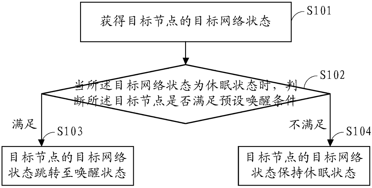
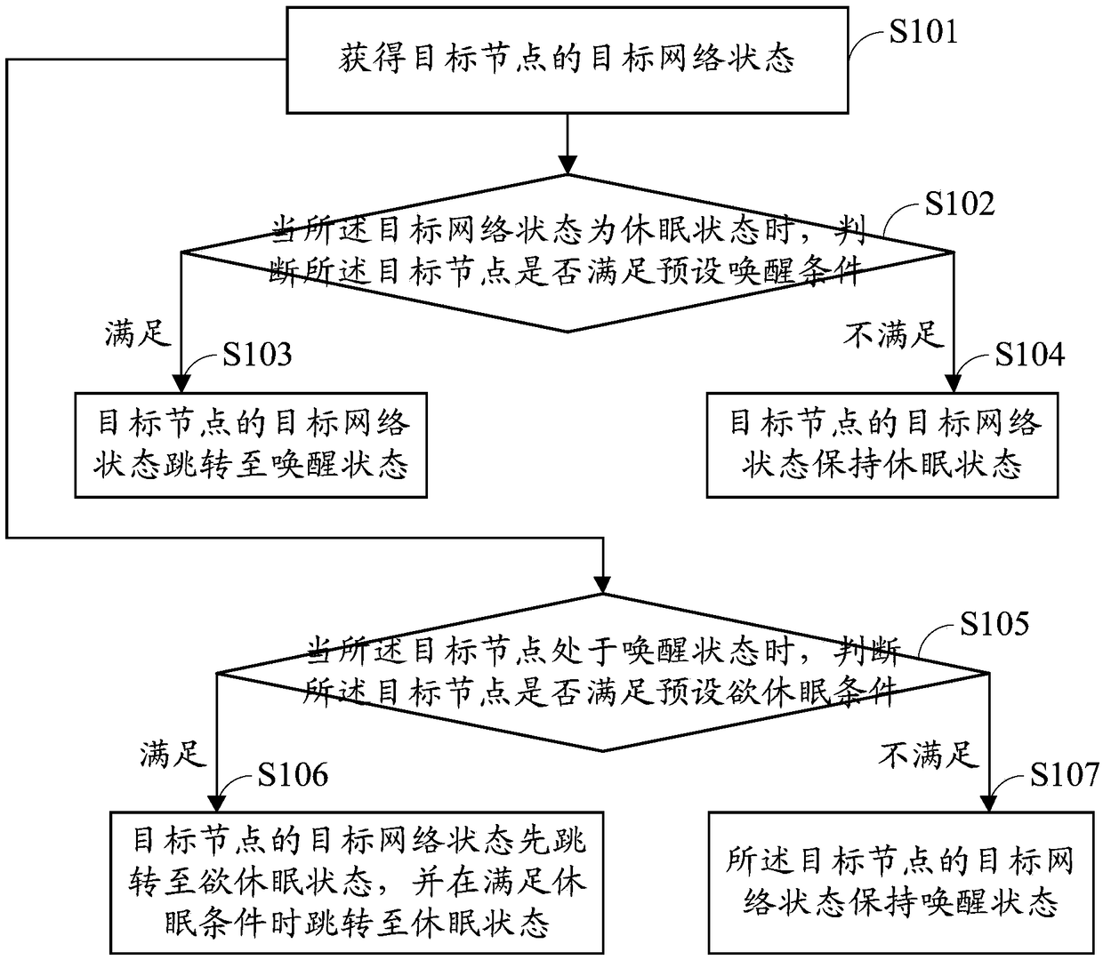
The embodiment of the invention provides a CAN (Controller Area Network)-bus-based network management method and system. The CAN-bus-based network management method is applied to each target node in the same CAN network. The CAN-bus-based network management method includes the steps: acquiring the target network state of target nodes, wherein the network state at least includes a dormant state anda wake-up state; and when the target network state is in the dormant state, determining whether the target nodes meet the preset wake-up conditions, wherein if so, the target network state of the corresponding target node jumps to the wake-up state, and if not, the target network state of the corresponding target node remains in the dormant state. When the CAN-bus-based network management methodis used to perform network management, each node in the network is executed according to the above scheme, and no cascading effect exists between each node. Therefore, each node can be in the dormantstate or the wake-up state according to the needs of the functional system in which the each node is located, thus reducing unnecessary waste of waiting for the remaining nodes on the network to be inthe dormant state or to wake up by the remaining nodes without performing the corresponding functions.

Description

Technical field [0001] The invention relates to the technical field of network management, in particular to a network management method and system based on CAN bus. Background technique [0002] Currently, network management of vehicles is one of the important applications of CAN (Controller Area Network) bus. Generally, ECUs (Electronic Control Units) in various functional systems of a vehicle are built into a CAN network based on the CAN bus. The network management of a vehicle mainly manages sleep and wake-up of nodes with each ECU as a node. When the CAN network node is in the dormant state, it can effectively reduce the power consumption of the on-board battery, so that the on-board battery can have a longer standby time. [0003] Nowadays, the vehicle’s own network management mostly adopts the German open systems and the corresponding interfaces for automotive electronics (OSEK) network management mechanism. The OSEK mechanism has the following synchronization characteristic...

Claims


Application Information

Patent Timeline
IPC IPC(8): H04L12/12H04L12/40
CPCH04L12/12H04L12/40006H04L2012/40215H04L2012/40273Y02D30/50
Inventor 龚存昊王玮杨法松刘晓军陈龙高政
Owner ANHUI JIANGHUAI AUTOMOBILE GRP CORP LTD
Why Eureka
Try Eureka