
Self-locking type manual pressure machine
A press, self-locking technology, applied in the direction of presses, stamping machines, metal processing, etc., can solve the problems of unfavorable workpiece alignment molded workpieces, no self-locking function, unable to maintain pressure, etc.
- Summary
- Abstract
- Description
- Claims
- Application Information
AI Technical Summary
Problems solved by technology
Method used
Image

Examples
Embodiment Construction
[0014] The present invention will be described in detail below in conjunction with the accompanying drawings.
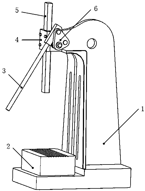
[0015] A self-locking manual press mainly consists of a body 1, a workbench 2, a pressure rod 3, a pressure head 5, a connecting plate 6 and some transmission mechanisms.
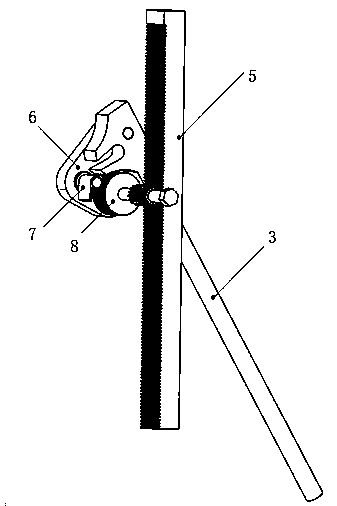
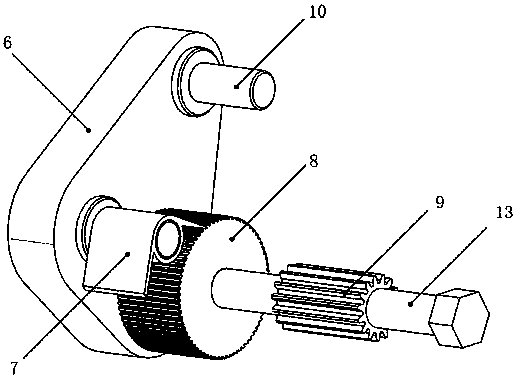
[0016] The workbench 2 is placed on the body 1, the surface of the workbench 2 is set with a T-shaped groove for positioning connection, the pressure head 5 is connected with the gear of the body 1 through the pressure plate 4, and the back of the pressure head 5 is a trapezoidal tooth surface; the gear 9 is fixedly connected on the main shaft 13, and the main shaft 13 is installed on the fuselage 1; the ratchet 8 is set on the outside of the main shaft 13, and is fixedly connected with the main shaft 13; the pawl 7 is hinged with the pin rod 11 on the connecting plate 6, and the connecting plate 6 and The main shaft 13 is hinged, the pressure rod 3 is hinged with the pin 10 on the connecting plat...
PUM
 Abstract
Description
Claims
Application Information