
Selective punching device

A punching device and punching technology, used in metal processing, metal processing equipment, manufacturing tools, etc., can solve the problems of low precision, inability to increase or decrease punching, and single performance, and achieve the effect of high punching precision.

Inactive Publication Date: 2018-11-30
苏州市翔耀精密自动化设备有限公司
View PDF10 Cites 0 Cited by
  • Summary
  • Abstract
  • Description
  • Claims
  • Application Information

AI Technical Summary

Problems solved by technology

However, today's punching machines often cannot increase or decrease the number of punching holes according to the demand, and the performance is single and the scope of application is narrow.
[0003] In addition, due to the unreasonable design of many punching machines on the market, the final product obtained is rough and has low precision.

Method used


Image

  • Selective punching device
  • Selective punching device
  • Selective punching device

Examples


Embodiment

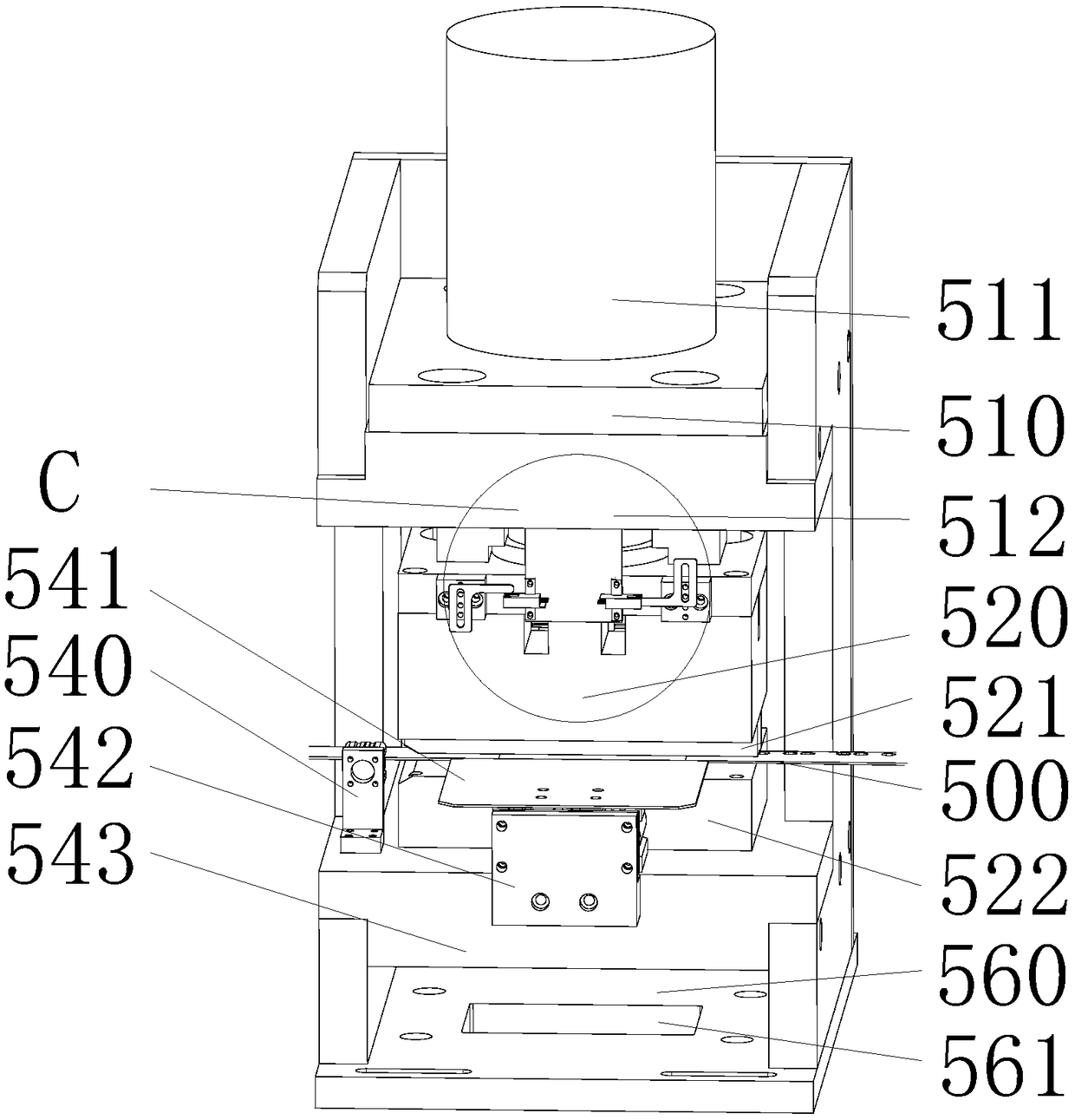
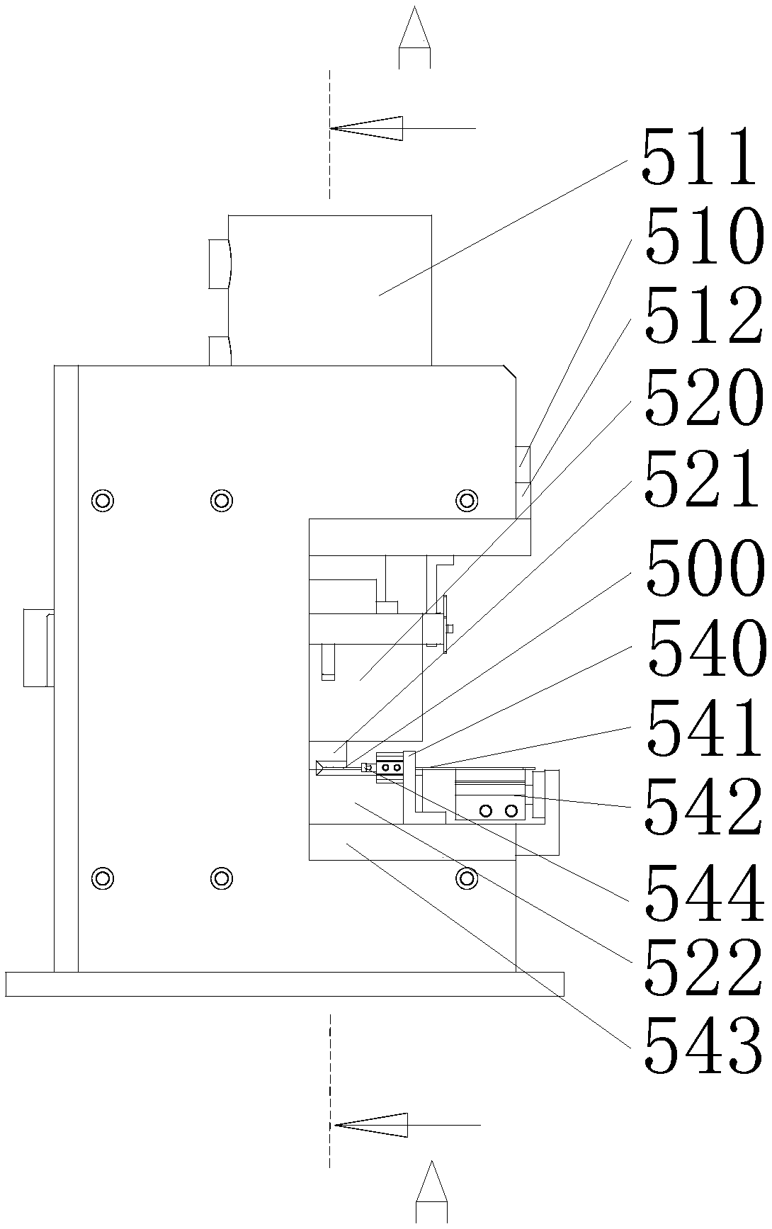
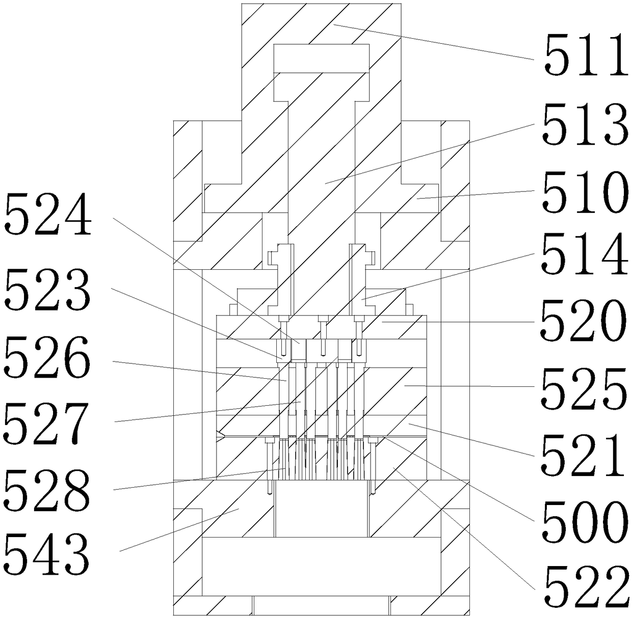
[0027] Reference Figure 1 ~ Figure 6 As shown, the present invention discloses a selective punching device, which includes a selective punching module and a driving module that provides power for the selective punching module.

[0028] Such as figure 1 Shown here is a schematic structural diagram of the device. The driving module includes a driving source backplane 510 and a driving source 511 arranged on the driving source backplane 510, and a fixing seat 512 is fixedly arranged on the lower side of the driving source backplane 510. A selective punch module is provided on the lower side of the driving module. The selective punch module includes a punching top plate 520 and a punch provided on the punching top plate 520. Under the control of the driving source 511, the punching top plate 520 can drive the punch to move up and down relative to the fixed seat 512, thereby completing the punching operation. A movement limit module C is provided between the fixing base 512 and the ...


PUM


Abstract

The invention discloses a selective punching device comprising a selective punch module and a driving module for powering the selective punch module. The selective punch module includes punches and anadjusting plate, the punches move up and down and abut to punch a steel belt, the number of the punches is a lot, the adjusting plate can move in a front-rear direction and adjust the stamping intensity of at least one punch, the upper side of each punch is provided with a cavity, the adjusting plate can move in the horizontal direction and fills the cavity, the up-and-down depth of the cavity isgreater than the movement distance of the punch, and the driving module includes a driving source capable of providing power and a moving end outputting power outwards to make punched holes move up and down. The selective punching device can selectively punch holes and is high in precision, compact in structure and wide in application range.

Description

Technical field [0001] The invention relates to the technical field of mechanical processing, in particular to a selective punching device. Background technique [0002] At present, many mechanical processing needs to punch holes on the steel belt to produce products of different specifications. However, the current punching machine often cannot increase or reduce the number of punching holes according to demand, because of its single performance and narrow application range. [0003] In addition, due to unreasonable design of many punching machines on the market, the final product obtained is rough and low in accuracy. Summary of the invention [0004] The technical problem to be solved by the present invention is to provide a selective punching device, which can selectively punch holes, has high precision, compact structure and wide application range. [0005] In order to solve the above technical problems, the present invention provides a selective punching device, including a se...

Claims


Application Information

Patent Timeline
Patent Type & Authority Applications(China)
IPC IPC(8): B21D28/26B21C51/00
CPCB21D28/26B21C51/00
Inventor 许晓华
Owner 苏州市翔耀精密自动化设备有限公司
Learn More