Cement casting die for manufacturing of electric wire pole

A technology for pouring molds and utility poles, applied in molds and other directions, can solve the problems of high cost, easy to roll, rupture and scrap, etc., and achieve the effect of improving service life, preventing slurry running, and saving production time.

Inactive Publication Date: 2018-11-30
无为县红宇通信器材有限责任公司
View PDF4 Cites 11 Cited by
  • Summary
  • Abstract
  • Description
  • Claims
  • Application Information

AI Technical Summary

Problems solved by technology

[0002] Generally, the shape of the utility pole mold device is relatively ordinary. After the production is completed, it is easy to roll, resulting in desizing of the utility pole inside the mold, or even breaking and scrapping.
With the improvement of science and technology, the factory has higher and higher requirements for production quality, and the structure of the utility pole mold device in the factory is complicated. Although the production quantity is guaranteed, it is not stable.
[0003] At present, most of the traditional installation methods of electric pole molds are controlled by mechanical buttons, which is inconvenient to operate, low in integration, and the mold needs to be replaced regularly, which is costly and easy to run out.

Method used


Image

  • Cement casting die for manufacturing of electric wire pole
  • Cement casting die for manufacturing of electric wire pole
  • Cement casting die for manufacturing of electric wire pole

Examples


Embodiment Construction

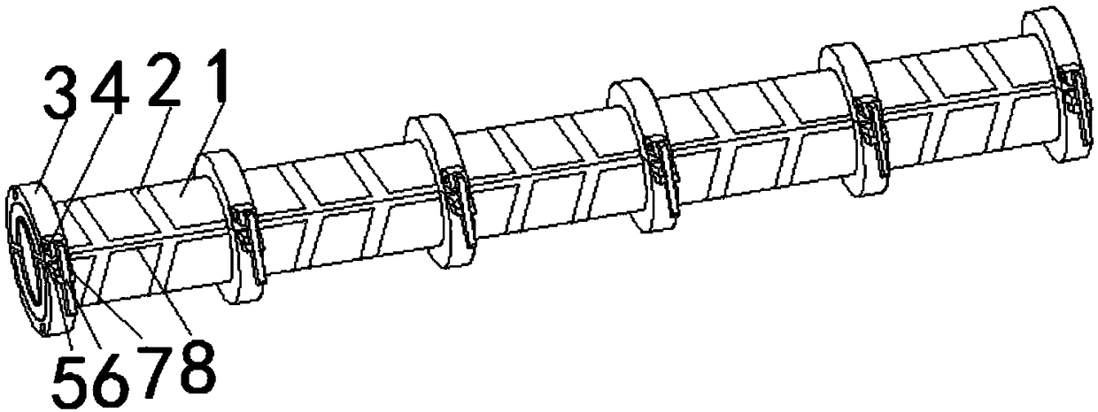
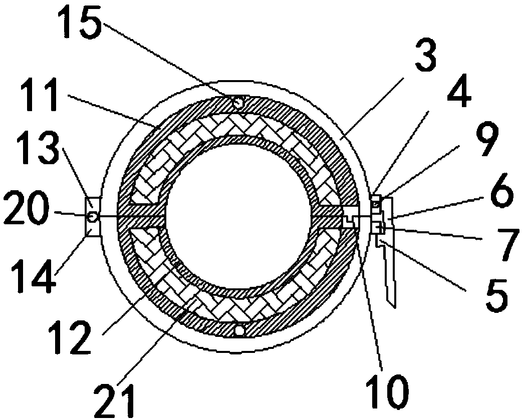
[0021] Such as Figure 1-Figure 4 As shown, a cement pouring mold for the manufacture of utility poles proposed by the present invention includes a mold body 1, longitudinal ribs 2 and reinforcement seats 3, and a plurality of reinforcement seats 3 are arranged on the mold body 1, and the interior of the reinforcement seats 3 is set There is an upper mold 11, a lower mold 12 is arranged symmetrically with the upper mold distance 11 in the reinforcement seat 3, and a buffer layer 21 is arranged in the upper film tool 11 and the lower mold 12;

[0022] Reinforcement seat 3 is composed of upper and lower parts. The left side of the upper part of reinforcement seat 3 is provided with an upper flip fixed block 13. The upper flip fixed block 13 is rotationally connected with the lower flip fixed block 14 through the second rotating shaft 20. The right side is provided with a lock support block 4, the lock support block 4 is connected to the upper end of the locking handle 6 through ...


PUM


Abstract

The invention discloses a cement casting die for manufacturing of an electric wire pole. The cement casting die comprises a die body, longitudinal reinforcing ribs and a plurality of reinforcing seats, wherein the multiple reinforcing seats are arranged on the die body; an upper die is arranged in each reinforcing seat; a lower die is arranged in each reinforcing seat and is symmetric to the corresponding upper die; buffer layers are respectively arranged in each upper die and each lower die; each reinforcing seat consists of an upper part and a lower part; an upper turnover fixed block is arranged at the left side of the upper half part of each reinforcing seat, and is rotationally connected with a lower turnover fixed block through a second rotary shaft. The cement casting die has the advantages that in the use process, each upper die is opened, a reinforcement cage of the electric wire pole is put into each lower die, a proper amount of concrete is cast, then each upper die is closed, a convex block at the lower side of the right end of each upper die is inserted into a groove, and the die can be stabilized; a locking press handle is pressed down, and a clamp block is clamped with a locking block, so that the die can be directly and effectively tightened, the step of fixing and tightening the bolt in the traditional bolt is not required, and the production time is shortened.

Description

technical field [0001] The invention relates to the technical field of pouring molds, in particular to a cement pouring mold used for manufacturing utility poles. Background technique [0002] Generally, the shape of the utility pole mold device is relatively ordinary. After the production is completed, it is easy to roll, resulting in desizing of the utility pole inside the mold, or even breaking and scrapping. With the improvement of science and technology, the factory has higher and higher requirements for production quality, and the structure of the utility pole mold device in the factory is complicated. Although the production quantity is guaranteed, it is not stable. [0003] At present, most of the traditional installation methods of electric pole molds are controlled by mechanical buttons, which is inconvenient to operate, low in integration, and the mold needs to be replaced regularly, which is costly and easy to run out. Therefore, those skilled in the art provide...

Claims


Application Information

Patent Timeline
Patent Type & Authority Applications(China)
IPC IPC(8): B28B21/82
CPCB28B21/82
Inventor 范宏秀
Owner 无为县红宇通信器材有限责任公司
Why Eureka
Try Eureka