
Automatic overturning mechanism and automatic overturning device

An automatic flipping and flipping bar technology, which is applied in the direction of conveyors, conveyor objects, transportation and packaging, etc., can solve problems such as error-prone, low efficiency of manual flipping, and large space occupation

Inactive Publication Date: 2018-11-30
ZHOUSHAN LEIDA ELECTRICAL TECH
View PDF7 Cites 5 Cited by
  • Summary
  • Abstract
  • Description
  • Claims
  • Application Information

AI Technical Summary

Problems solved by technology

As far as the current overturning method is concerned, manual overturning is inefficient and prone to errors; the automatic overturning device has a longitudinal overturning device along the conveying device and a horizontal overturning device, but it must have two 90-degree overturns, which takes up a lot of space. Long packing cartons or flat packing cartons are not suitable, so the existing turning method needs to be optimized

Method used


Image

  • Automatic overturning mechanism and automatic overturning device
  • Automatic overturning mechanism and automatic overturning device
  • Automatic overturning mechanism and automatic overturning device

Examples


Embodiment 1

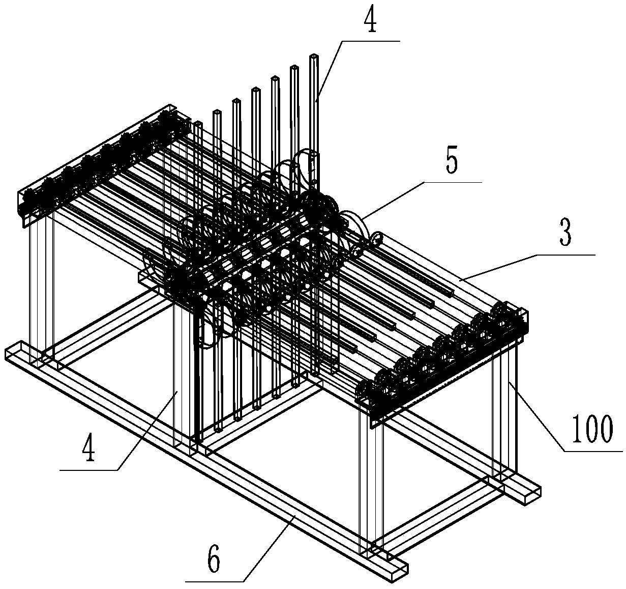
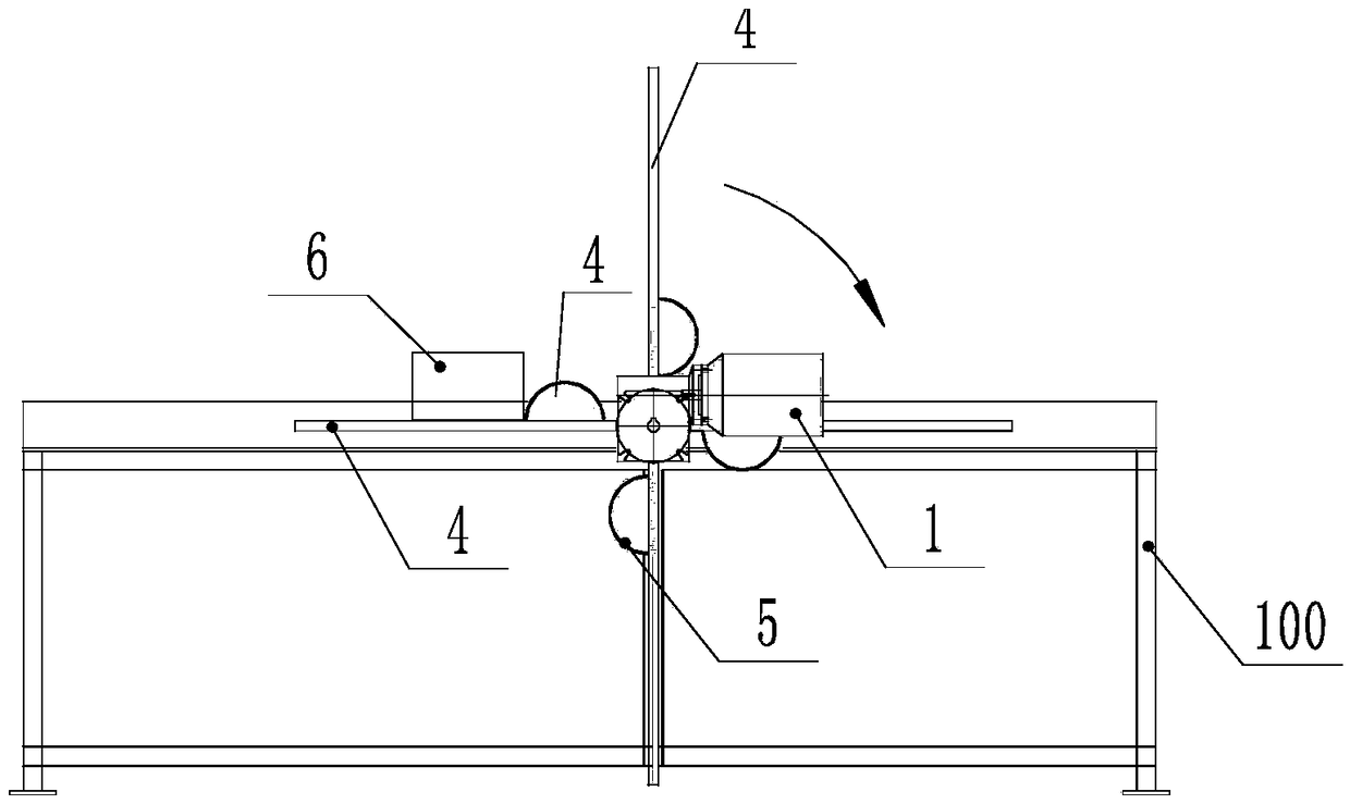
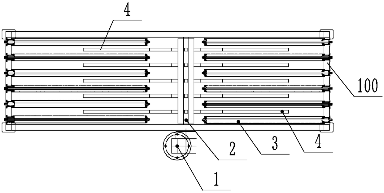
[0029] An automatic turning mechanism, comprising a driving motor 1, a rotating shaft 2, a turning lever 4 and a limit ring 5, the driving motor 1 is a stepping motor, the rotating shaft 2 is in transmission connection with the driving motor 1, and the turning lever 4. There are several groups, and each group of turning rods 4 is fixedly connected to the rotating shaft 2, and each group of turning rods 4 is distributed on the outer periphery of the rotating shaft 2 in a cross shape with the rotating shaft 2 as the center of symmetry; in this embodiment, each group There are four overturning levers 4, each overturning lever 4 is perpendicular to the axis of the rotating shaft 2, and two adjacent overturning levers 4 are perpendicular to each other. In order to treat the flipped items 6 to realize the limit during the flipping process, such as figure 1 and 2 As shown, a limiting ring 5 is provided on each turning lever 4, and the limiting ring 5 is fixedly connected with the tu...

Embodiment 2

[0031] An automatic turning device, comprising the automatic turning mechanism in Embodiment 1, also includes a frame 100, a transmission structure and a buffer device, in the present embodiment, the transmission structure is a transmission roller 3, and the buffer device is an elastic strip ( not marked). The stepper motor is fixedly installed on the frame 100 . There are several driving rollers 3, and each driving roller 3 is rotatable relative to the frame 100, and the driving rollers 3 are symmetrically arranged in two rows on the cargo conveying line. To realize the turning over of the article 6 is to turn the article 6 over 180° from one row of drive rollers 3 to the other row of drive rollers 3 . The elastic strip is fixedly arranged on the outer surface of the transmission roller 3, so that the article 6 can fall on another row of transmission rollers 3 stably, reducing the impact force. In other embodiments, the buffer device can also be an elastic member directly f...


PUM


Abstract

The invention discloses an automatic overturning mechanism and an overturning device. The automatic overturning mechanism comprises a driving motor, a rotating shaft, overturning rods and limiting rings. The rotating shaft is in transmission connection with the driving motor. The multiple groups of overturning rods are arranged. Each group of overturning rods is fixedly connected with the rotatingshaft. Each group of overturning rods takes the rotating shaft as a symmetrical center and is distributed on the periphery of the rotating shaft in a cross shape. The overturning device comprises theoverturning mechanism and further comprises a frame, a transmission structure and a buffer device. By the adoption of the automatic overturning mechanism and the automatic overturning device, it canbe ensured that an article can be overturned by 180 degrees in one action, so that the article can receive uniform irradiation dose.

Description

technical field [0001] The invention relates to an overturning device, in particular to an automatic overturning device for an irradiation accelerator. Background technique [0002] Electron accelerators are used for ray irradiation. Due to energy limitations, the range of electron ray in the irradiated object is limited. In order to make the irradiated object receive a uniform radiation dose, usually when the carton package is irradiated under the accelerator beam At any time, it is necessary to turn it over after one irradiation and then accept another irradiation. As far as the current overturning method is concerned, manual overturning is inefficient and prone to errors; the automatic overturning device has a longitudinal overturning device along the conveying device and a horizontal overturning device, but it must have two 90-degree overturns, which takes up a lot of space. Long packing cartons or flat packing cartons are not suitable, so the existing turning method ne...

Claims


Application Information

Patent Timeline
Patent Type & Authority Applications(China)
IPC IPC(8): B65G47/248
CPCB65G47/248B65G2201/025
Inventor 王方舟虞强韩军
Owner ZHOUSHAN LEIDA ELECTRICAL TECH
Learn More