

Sliding supporting seat utilizing hydraulic hammer guide grooves to guide displacement
A technology of hydraulic hammer and support seat, which is applied in construction, sheet pile wall, foundation structure engineering, etc., can solve the problems of complicated and time-consuming process, large manpower labor, etc., achieve the effect of simple structure, convenient use, and avoid frequent disassembly of hydraulic hammer
- Summary
- Abstract
- Description
- Claims
- Application Information
AI Technical Summary
Problems solved by technology
Method used
Image

Examples
Embodiment Construction
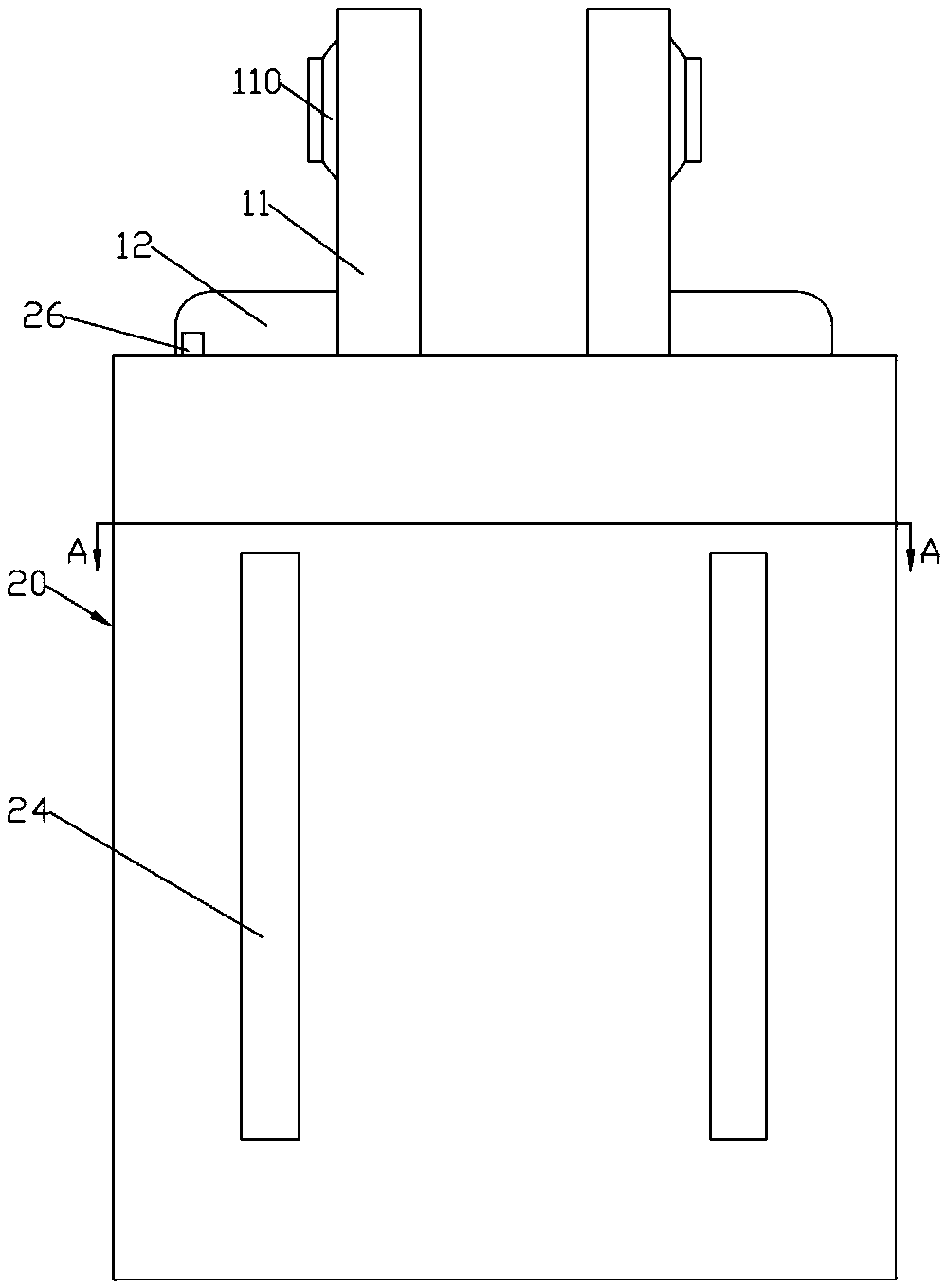
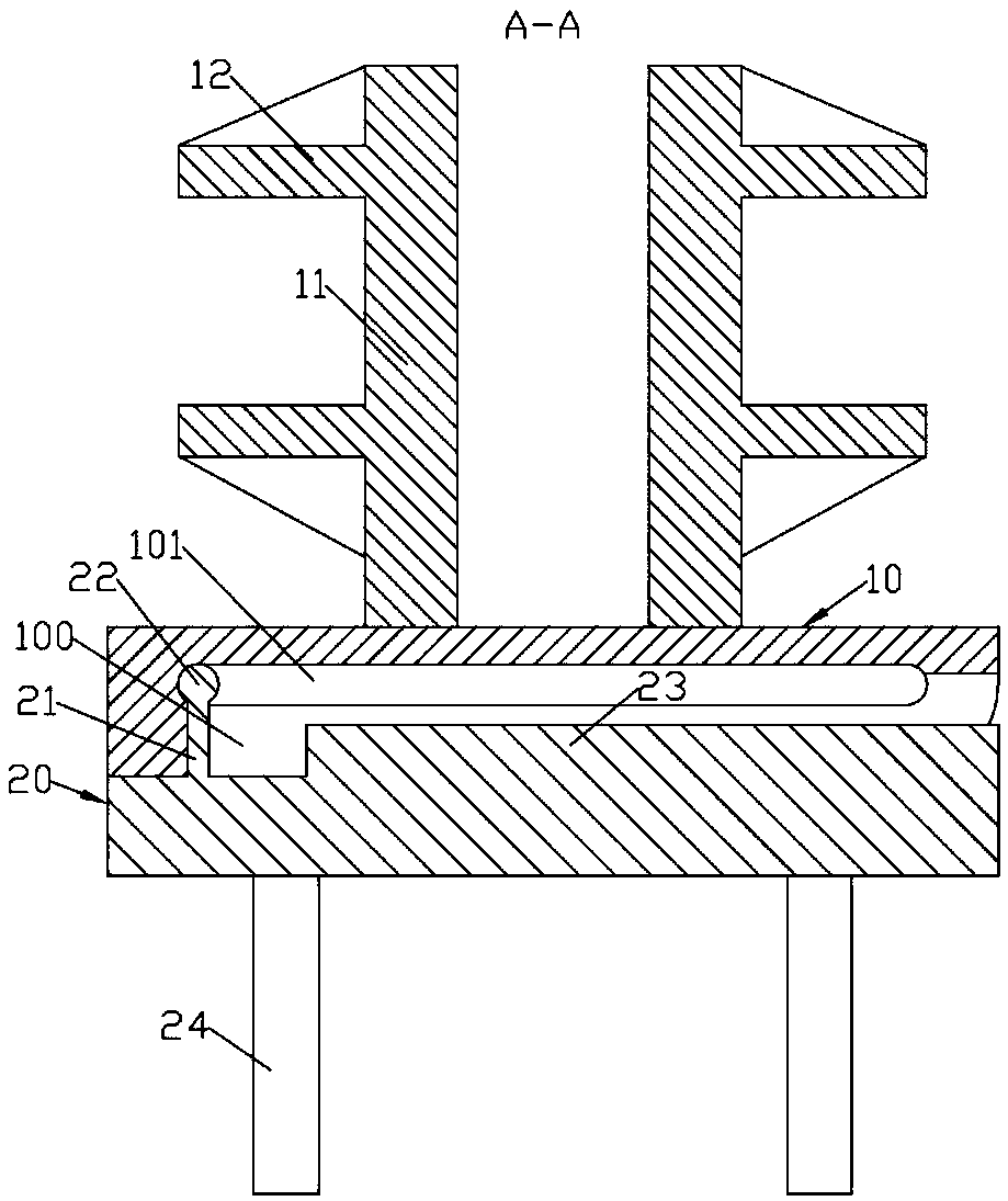
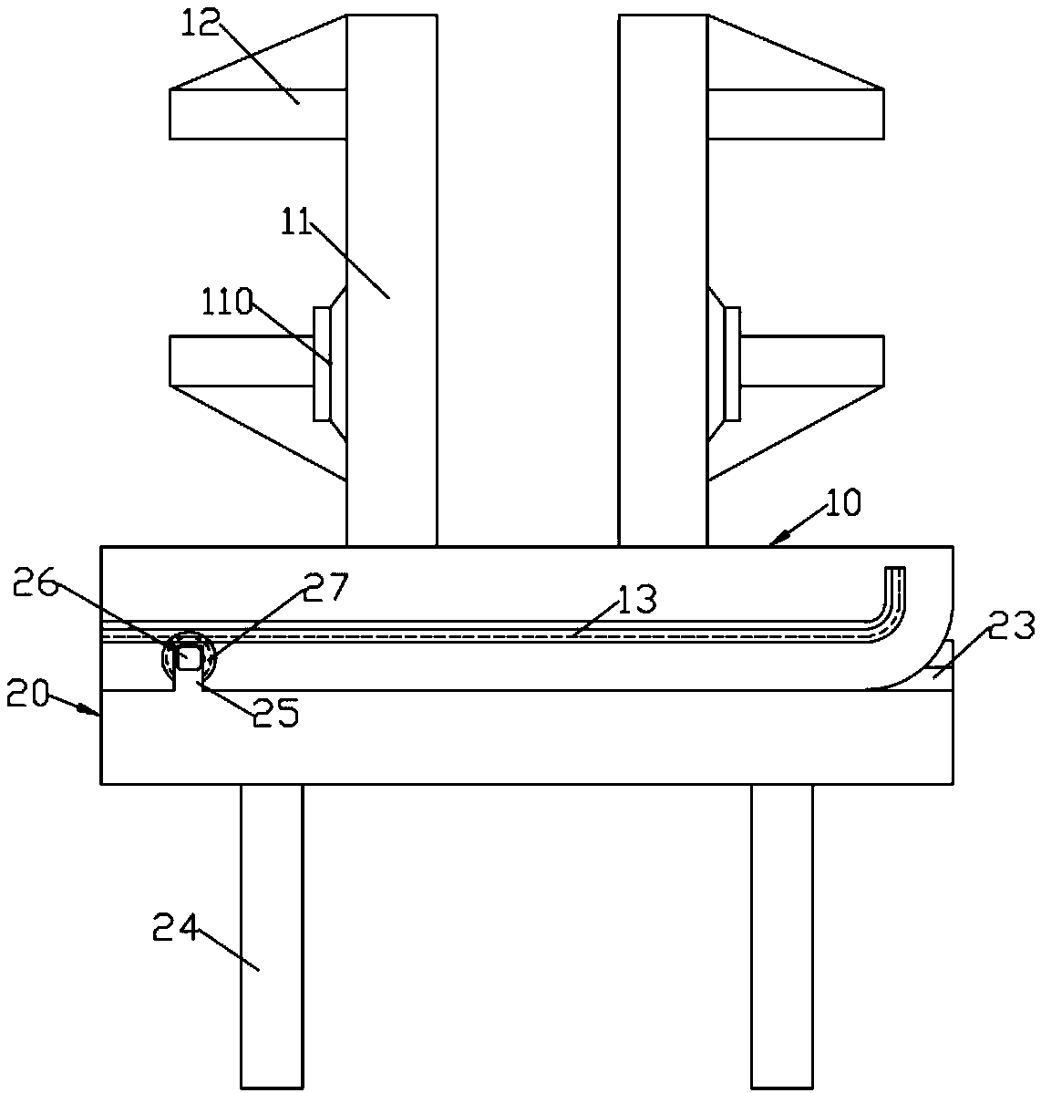
[0017] Such as Figure 1 to Figure 6 As shown in the figure, a sliding support seat guided by a hydraulic hammer guide groove includes a rectangular main support plate 10 and a secondary support plate 20; a pair of left and right symmetrical sliding plates 11 are vertically welded on the rear end surface of the main support plate 10; The inside of the support plate 10 is formed with a number of long hole-shaped sliding grooves 101 distributed up and down; the front part of the sliding groove 101 and the middle part of the side wall of the right part are provided with guide grooves 100; A number of guide blocks 21 distributed up and down that cooperate with the guide groove 100; the rear end of the guide block 21 is formed with a cylindrical sliding column 22 and the upper and lower ends of the sliding column 22 respectively exceed the upper and lower end surfaces of the guide block 21; the guide block 21 slides to set In the guide groove 100; the sliding column 22 slides and i...
PUM
 Abstract
Description
Claims
Application Information