
Pole guy winding device

A technology for pulling wires and winders of electric poles, which is applied to building types, buildings, towers, etc., can solve the problems of reducing the service life of tools, wear of tool surfaces, and burrs that are easy to scratch people, so as to reduce wear, prolong service life, and avoid glitch effect

Pending Publication Date: 2018-11-30
STATE GRID JIANGSU ELECTRIC POWER CO LTD NANTONG POWER SUPPLY BRANCH
View PDF0 Cites 2 Cited by
  • Summary
  • Abstract
  • Description
  • Claims
  • Application Information

AI Technical Summary

Problems solved by technology

[0003] In the prior art, there are still deficiencies in the pole pull wire winder, which lacks an anti-wear structure, and the iron wire is easy to cause wear on the surface of the tool during the winding process, which not only reduces the service life of the tool, but also easily scratches the burrs caused by sliding friction. Injury personnel, so a new type of pole stay wire winder is needed to solve the above-mentioned problems

Method used


Image

  • Pole guy winding device
  • Pole guy winding device

Examples


Embodiment Construction

[0017] In order to make the technical means, creative features, goals and effects achieved by the present invention easy to understand, the present invention will be further described below in conjunction with specific embodiments.

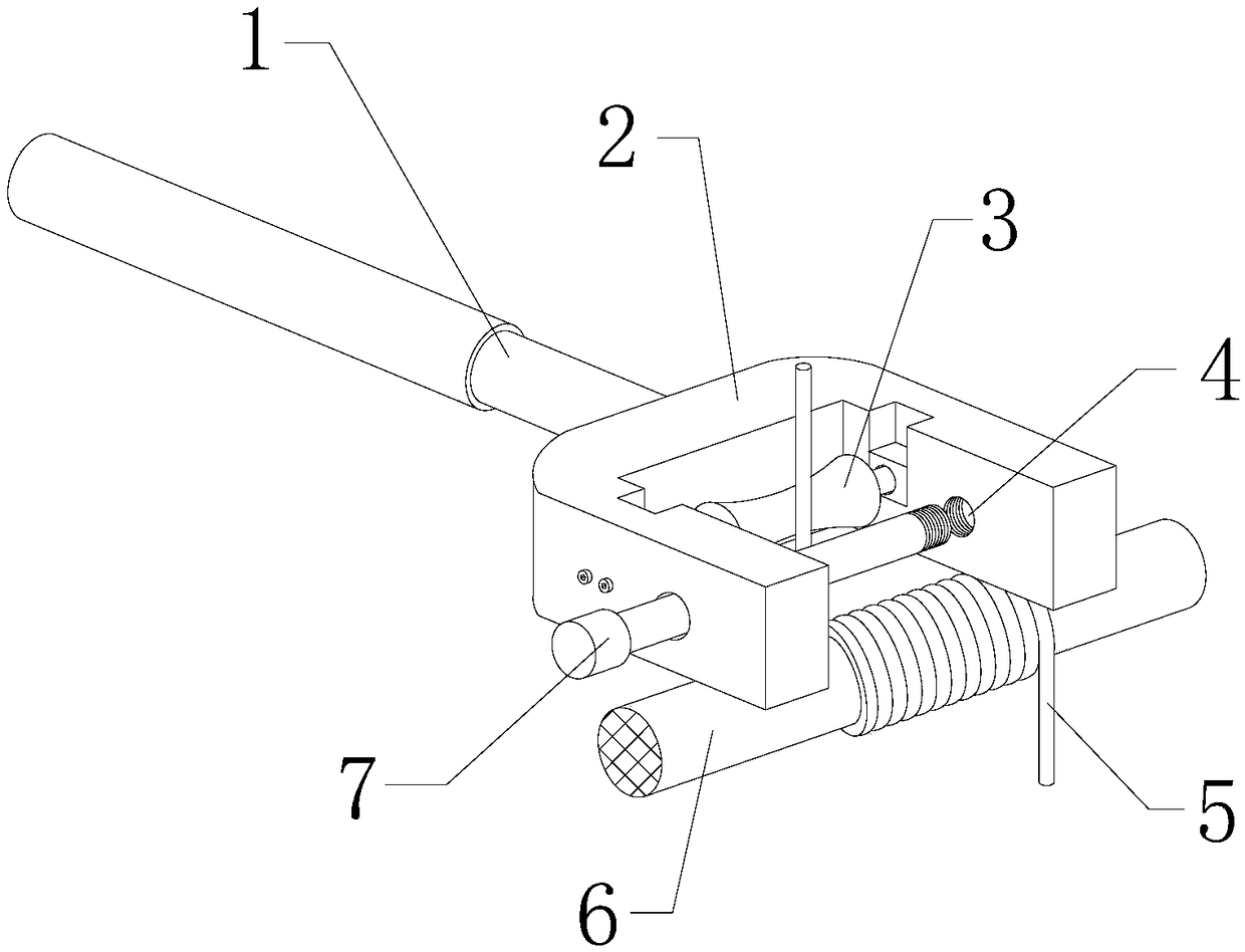
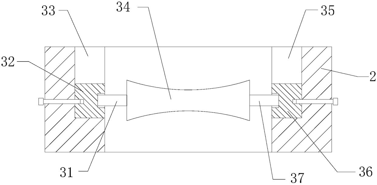
[0018] see figure 1 and figure 2 , the present invention provides a technical solution: a pole stay wire winder, including a handle 1, a U-shaped frame 2, an anti-wear component 3, an iron wire 5, a stay wire 6 and a limit rod 7, and the iron wire 5 is wound on the annular side of the stay wire 6 On the upper side, the handle 1 is fixed in the middle of the left end surface of the U-shaped frame 2, and the right side of the rear end surface of the U-shaped frame 2 is provided with a threaded blind hole 4, and the rear end of the limit rod 7 passes through the front surface of the U-shaped frame 2 and is installed on the threaded Inside the blind hole 4.

[0019] The anti-wear assembly 3 includes a rotating shaft 1 31, a limiting block 1 32, a s...


PUM


Abstract

The invention provides a pole guy winding device. The pole guy winding device comprises a first rotating shaft, a first limiting block, a first inserting groove, a pressing roller, a second insertinggroove, a second limiting block and a second rotating shaft, wherein the first inserting groove is formed in the left side of the front end surface inside a U-shaped frame, the second inserting grooveis formed in the left side of the rear end surface inside the U-shaped frame, the first limiting block is installed in the first inserting groove in an inserting mode, and the second limiting block is installed in the second inserting groove in an inserting mode; the rear end of the first rotating shaft is fixed in the middle of the front end surface of the pressing roller, and the front end of the first rotating shaft is installed on the rear end surface of the first limiting block; and the front end of the second rotating shaft is fixed at the middle position of the rear end surface of thepressing roller, and the rear end of the first rotating shaft is installed on the front end surface of the second limiting block. The design utilizes the rolling friction between the pressing roller and an iron wire in the process of pressing and holding a steel wire to reduce the abrasion of the iron wire to the U-shaped frame. The pole guy winding device is convenient to use and simple to operate, has an anti-abrasion function, and is convenient to carry.

Description

technical field [0001] The invention relates to a pole stay wire winder, which belongs to the field of power grid auxiliary equipment. Background technique [0002] During the erection of the pole, it is necessary to adjust the force of the pole in all directions to ensure that the force of the pole is balanced in all directions. Usually, the poles are equidistantly arranged outside the circumference of the pole. When the pole stay wire is connected, one end is usually bent and then connected with a rope buckle to form a closed ring for easy connection with other components. For the steel wire rope head and its loose steel wire, it is necessary to use iron wire to wind it. In order to prevent the wire rope head from hurting people, it is also beneficial to strengthen the connection of the wire rope. [0003] In the prior art, there are still deficiencies in the pole pull wire winder. It lacks an anti-wear structure, and the iron wire is easy to cause wear on the surface of ...

Claims


Application Information

Patent Timeline
IPC IPC(8): E04H12/20
CPCE04H12/20
Inventor 黄霆张乐刘飞陈葛亮
Owner STATE GRID JIANGSU ELECTRIC POWER CO LTD NANTONG POWER SUPPLY BRANCH
Learn More