Image identification method and device, and electronic equipment

An image recognition and image acquisition device technology, applied in the field of image processing, can solve problems such as illegal user attacks of the face recognition system, and achieve the effect of improving performance and robustness

Inactive Publication Date: 2018-11-30
BEIJING KUANGSHI TECH
View PDF7 Cites 4 Cited by
  • Summary
  • Abstract
  • Description
  • Claims
  • Application Information

AI Technical Summary

Problems solved by technology

However, the face recognition system is also vulnerable to some illegal users

Method used


Image

  • Image identification method and device, and electronic equipment
  • Image identification method and device, and electronic equipment
  • Image identification method and device, and electronic equipment

Examples


Embodiment 1

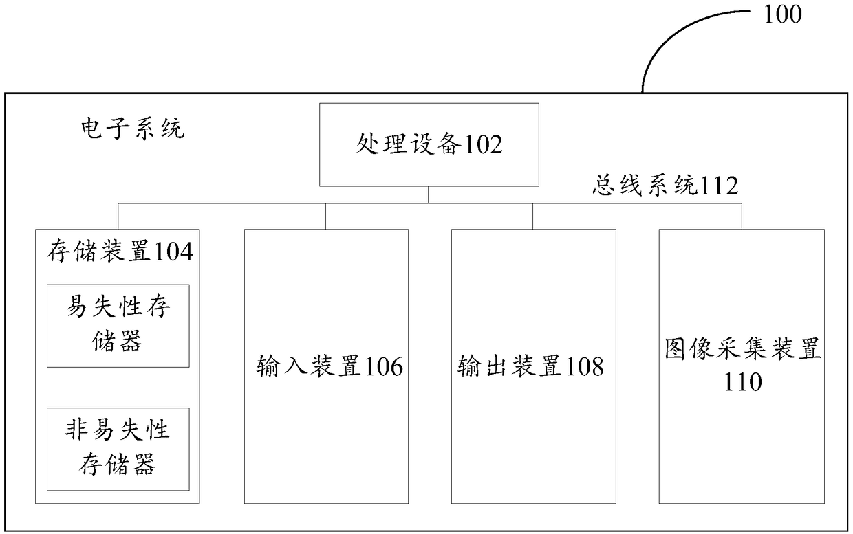
[0055] First, refer to figure 1 An example electronic device 100 for implementing the scene recognition method of the embodiment of the present invention will be described. The electronic device 100 in this example may be a computer, a mobile terminal such as a smart phone or a tablet computer, or an authentication device such as an all-in-one personal identification machine.

[0056] Such as figure 1 As shown, the electronic device 100 includes one or more processors 102, one or more storage devices 104, an input device 106, an output device 108, and an image acquisition device 110, and these components are connected through a bus system 112 and / or other forms of connection mechanisms (not shown) interconnects. It should be noted that figure 1 The components and structure of the electronic device 100 shown are only exemplary, not limiting, and the electronic device may also have other components and structures as required.

[0057] The processor 102 may be a central proce...

Embodiment 2

[0066] This embodiment provides an image recognition method, which can be executed by an electronic device.

[0067] According to an embodiment of the present invention, an embodiment of an image recognition method is provided. It should be noted that the steps shown in the flowcharts of the accompanying drawings can be executed in a computer system such as a set of computer-executable instructions, and, although A logical order is shown in the flowcharts, but in some cases the steps shown or described may be performed in an order different from that shown or described herein.

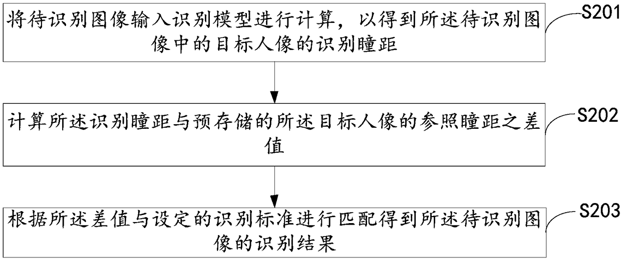
[0068] see figure 2 , is a flow chart of the image recognition method provided by the embodiment of the present invention. The following will be figure 2 The specific process shown will be described in detail.

[0069] Step S201, input the image to be recognized into the recognition model for calculation, so as to obtain the recognition pupil distance of the target portrait in the image to be reco...

Embodiment 3

[0127] Corresponding to the image recognition method provided in Embodiment 2, this embodiment provides an image recognition device. Each module in the image recognition device in this embodiment is used to execute the steps in the method in the second embodiment. Figure 4 A schematic structural diagram of an image recognition device provided by an embodiment of the present invention is shown, as shown in Figure 4 As shown, the device includes the following modules.

[0128] The first calculation module 401 is configured to input the image to be recognized into the recognition model for calculation, so as to obtain the recognition pupil distance of the target portrait in the image to be recognized.

[0129] The second calculation module 402 is configured to calculate the difference between the identified pupillary distance and the pre-stored reference pupillary distance of the target portrait.

[0130] The matching module 403 is configured to match the difference with a se...


PUM


Abstract

The embodiment of the invention provides an image identification method and device, and electronic equipment. In one embodiment, the image identification method comprises the following steps that: inputting an image to be identified into an identification model to be calculated to obtain the identification pupillary distance of a target portrait in the image to be identified; calculating a difference value between the identification pupillary distance and the pre-stored reference pupillary distance of the target portrait; and according to the difference value and a set identification standard,carrying out matching to obtain the identification result of the image to be identified, wherein the identification standard comprises a corresponding relationship between the difference value rangeof the identification pupillary distance and the reference pupillary distance and the identification result.

Description

technical field [0001] The present invention relates to the field of image processing, in particular to an image recognition method, device and electronic equipment. Background technique [0002] As an effective identity authentication and identification technology, face recognition technology has been widely used at present. However, the face recognition system is also vulnerable to some illegal users. There are three main types of attacks on face recognition systems: photo attacks, video attacks, and 3D model attacks. Criminals may try to deceive the system through photos, videos and 3D models of legitimate users in order to access the identification system. Contents of the invention [0003] In view of this, the purpose of the embodiments of the present invention is to provide an image recognition method, device and electronic equipment. [0004] In the first aspect, an image recognition method provided by an embodiment of the present invention includes: [0005] In...

Claims


Application Information

Patent Timeline
IPC IPC(8): G06K9/00
CPCG06V40/161G06V40/168G06V40/172G06V40/45
Inventor 何益升
Owner BEIJING KUANGSHI TECH
Why Eureka
Try Eureka