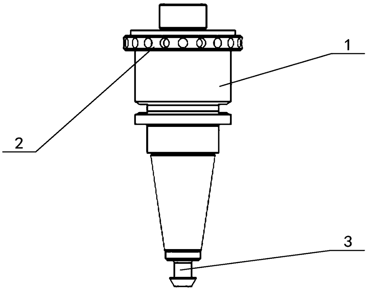
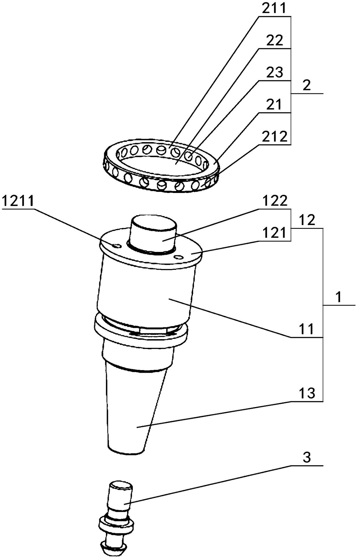
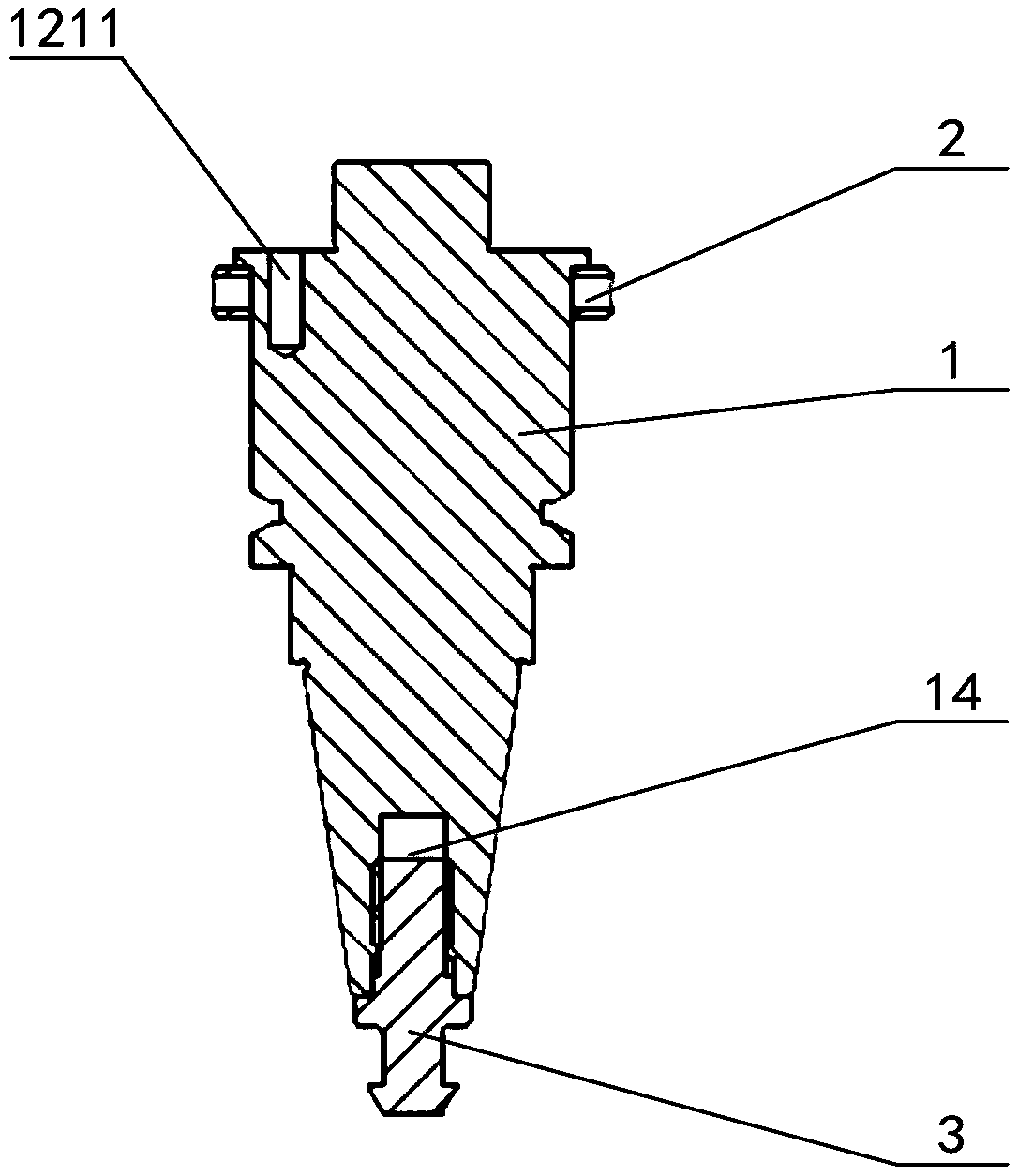
Dynamic balance knife handle

A technology of dynamic balance and tool handle, which is applied to the accessories of tool holders, manufacturing tools, metal processing machinery parts, etc., and can solve the problems of short service life of tool handles, unbalanced rotation, poor machining accuracy, etc.

Pending Publication Date: 2018-12-04
CONPROFE TECH GRP CO LTD +1
View PDF11 Cites 0 Cited by
  • Summary
  • Abstract
  • Description
  • Claims
  • Application Information

AI Technical Summary

Problems solved by technology

[0005] The purpose of the present invention is to provide a dynamic balance knife handle to solve the technical problems of poor machining accuracy and short service life of the existing knife handle which is prone to unbalanced rotation after being connected to the cutter head

Method used


Image

  • Dynamic balance knife handle
  • Dynamic balance knife handle
  • Dynamic balance knife handle

Examples


Embodiment Construction

[0023] The technical solutions of the present invention will be clearly and completely described below in conjunction with the accompanying drawings. Apparently, the described embodiments are some of the embodiments of the present invention, but not all of them. Based on the embodiments of the present invention, all other embodiments obtained by persons of ordinary skill in the art without making creative efforts belong to the protection scope of the present invention.

[0024] In the description of the present invention, it should be noted that the terms "center", "upper", "lower", "left", "right", "vertical", "horizontal", "inner", "outer" etc. The orientation or positional relationship indicated is based on the orientation or positional relationship shown in the drawings, and is only for the convenience of describing the present invention and simplifying the description, rather than indicating or implying that the system or component referred to must have a specific orientat...


PUM


Abstract

The invention discloses a dynamic balance knife handle, and relates to the technical field of machine tool machining. The problems that the machining precision is poor due to the fact that an existingknife handle is prone to be rotated and unbalanced after being connected with a cutterhead, and the service life of the knife handle is short are solved. The dynamic balance knife handle comprises aknife handle and a dynamic balance ring arranged on the knife handle, wherein the dynamic balance ring comprises a ring body, wherein the ring body is provided with an inner side face and an outer side face which are opposite to each other, the inner side face is used for enclosing a mounting hole in the middle of the ring body, and a plurality of counter weight holes are formed in the outer sideface of the ring body, and the plurality of counter weight holes are distributed along the circumferential direction of the outer side face; the knife handle comprises a knife handle main body, the mounting hole sleeves the knife handle main body; and a cutterhead mounting part is arranged at one end, close to the dynamic balance ring, of the knife handle main body, and a mounting shaft which is connected with a machine tool is arranged at the other end of the knife handle main body.

Description

technical field [0001] The invention relates to the technical field of machine tool processing, in particular to a dynamic balance tool holder. Background technique [0002] The tool handle is used to connect the machine tool spindle and the cutter head. The structure of the tool handle can affect the dynamic balance of the tool handle during the working process, thereby affecting the machining accuracy of the cutter head connected to it. [0003] The inventors of the present application found that in the structure of the tool handle provided by the prior art, since the main shaft drives the tool handle to rotate, there will be a phenomenon of unbalanced rotation, so it is easy to cause the radial runout and end surface of the cutter head after the cutter head is connected to the handle. The large runout affects the machining accuracy and also affects the service life of the tool holder. [0004] Therefore, how to provide a dynamically balanced tool handle, which can effect...

Claims


Application Information

Patent Timeline
IPC IPC(8): B23Q3/12B23B31/00
CPCB23B31/00B23Q3/12
Inventor 颜炳姜李伟秋林一松
Owner CONPROFE TECH GRP CO LTD
Why Eureka
Try Eureka