Ship crane for navigation height limit area

A technology for marine cranes and areas, which is applied in the direction of cranes, etc., can solve the problems of low traffic limit, limit the size of emergency rescue and salvage ships, restrict the application area of ​​marine cranes, etc., and achieve the effects of weight reduction, easy maintenance and installation space saving

Pending Publication Date: 2018-12-04
德马科起重机械有限公司
View PDF0 Cites 2 Cited by
  • Summary
  • Abstract
  • Description
  • Claims
  • Application Information

AI Technical Summary

Problems solved by technology

[0002] With the rapid development of inland water transport construction, the number of large inland transport ships is increasing, but the low navigation height limit requirements of some dams limit the size of emergency rescue and salvage ships, which seriously restricts the application area of ​​marine cranes; therefore, a A kind of marine crane used in the navigation height limit area

Method used


Image

  • Ship crane for navigation height limit area
  • Ship crane for navigation height limit area

Examples


Embodiment 1

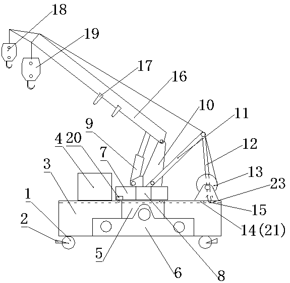
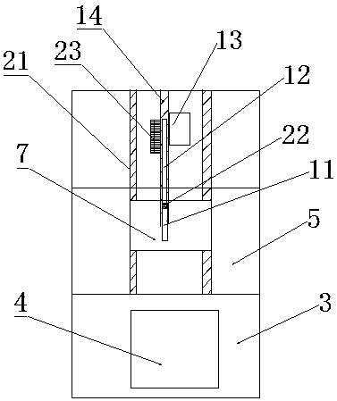
[0016] like Figure 1-2 As shown in the figure, a marine crane used in a navigable height-limited area includes a rotary drive platform 7, a support 5 is provided under the rotary drive platform 7, and a beam is provided on the left and right sides of the support 5 3. The crossbeam 3 and the lower part of the support 5 are fixedly connected by the balance beam 6, the wheel 1 is arranged under the crossbeam 3, and the rotary drive platform slideway 21 is arranged above the support 5 and the crossbeam 3 And the rear strut slideway 14, the rotary drive platform 7 is arranged above the said rotary drive platform slideway 21, the rear strut bar 12 is arranged on the said rear strut slideway 14, and the said rear strut slideway The side of 14 is provided with hinge seat 23, and described rear strut 12 is fixed on the hinge seat 23 by nut, and described rotary drive platform 7 and below rear strut 12 are all provided with roller 15, and described rotary drive The interior of the pla...

Embodiment 2

[0019] like Figure 1-2 As shown in the figure, a marine crane used in a navigable height-limited area includes a rotary drive platform 7, a support 5 is provided under the rotary drive platform 7, and a beam is provided on the left and right sides of the support 5 3. The crossbeam 3 and the lower part of the support 5 are fixedly connected by the balance beam 6, the wheel 1 is arranged under the crossbeam 3, and the rotary drive platform slideway 21 is arranged above the support 5 and the crossbeam 3 And the rear strut slideway 14, the rotary drive platform 7 is arranged above the said rotary drive platform slideway 21, the rear strut bar 12 is arranged on the said rear strut slideway 14, and the said rear strut slideway The side of 14 is provided with hinge seat 23, and described rear strut 12 is fixed on the hinge seat 23 by nut, and described rotary drive platform 7 and below rear strut 12 are all provided with roller 15, and described rotary drive The interior of the pla...


PUM


Abstract

The invention relates to a ship crane for a navigation height limit area. The ship crane comprises a revolution driving platform, a bearer is arranged under the revolution driving platform, crossbeamsare arranged at the left side and the right side of the bearer, a revolution driving platform slide way and a rear strut slide way are arranged above the beaer and the crossbeams, the revolution driving platform is arranged on the revolution driving platform slide way, a rear strut is arranged on the rear strut slide way, a hinge seat is arranged at the side part of the rear strut slide way, therear strut is fixed on the hinge seat through a nut, rollers are arranged under the revolution driving platform and the rear strut, a boom and a boom cylinder are arranged above the revolution drivingplatform, a lifting arm is hinged to the top of the boom, the cylinder body of the boom cylinder is hinged to the bottom of the boom, the end part of the piston rod of the boom cylinder is hinged tothe lifting arm, a front strut is hinged to the side part of the boom, and a hoist is arranged at the side part of the rear strut. The ship crane has the advantages of simplified structure, high reliability, excellent performances, and suitableness for the navigation height limit area.

Description

technical field [0001] The invention belongs to the technical field of marine cranes, and in particular relates to a marine crane used in a navigable height-limited area. Background technique [0002] With the rapid development of inland water transport construction, the number of large inland transport ships is increasing, but the low navigation height limit requirements of some dams limit the size of emergency rescue and salvage ships, which seriously restricts the application area of ​​marine cranes; therefore, a A marine crane used in areas with restricted heights for navigation. Contents of the invention [0003] The object of the present invention is to overcome the deficiencies of the prior art, and provide a marine crane for navigable height-limited areas with simplified structure, high reliability, and excellent performance, which is suitable for navigable height-limited areas. [0004] The purpose of the present invention is achieved in the following way: a mari...

Claims


Application Information

Patent Timeline
Patent Type & Authority Applications(China)
IPC IPC(8): B66C23/06B66C23/82B66C23/84B66C23/52
CPCB66C23/06B66C23/52B66C23/826B66C23/84
Inventor 董彦波毛义雪孔纯恒
Owner 德马科起重机械有限公司
Why Eureka
Try Eureka