A pipe jacking construction method

A construction method and pipe jacking technology, which is applied to sewer systems, waterway systems, buildings, etc., can solve problems such as many hidden dangers, large safety hazards, and short jacking length, and achieve the goals of saving investment, avoiding leakage, and facilitating construction Effect

Active Publication Date: 2020-08-25
CENT & SOUTHERN CHINA MUNICIPAL ENG DESIGN & RES INST CO LTD
View PDF9 Cites 0 Cited by
  • Summary
  • Abstract
  • Description
  • Claims
  • Application Information

AI Technical Summary

Problems solved by technology

[0005] Comparing the above two factors, it can be seen that if the pipe jacking design is set according to the maximum distance between the inspection wells required by the national standard, the pipe jacking working well and the pipe jacking receiving well will be set, and the length of each section of the pipe jacking will be short, which will not give full play to the advantages of the pipe jacking technology. Advantages, there are many pipe jacking working wells and pipe jacking receiving wells, and the project investment is relatively large
[0006] At present, it is popular in our country to adopt the method of riding a well to replace the pipe-jacking well to save investment and speed up the construction period, but from the actual implementation situation, it is not ideal and there are many hidden dangers
[0007] In recent years, riding wells are mostly constructed by manual digging, which has great potential safety hazards, and it is difficult to pass expert demonstrations and approval from relevant state departments; The quality is difficult to guarantee, and it is easy to cause leakage

Method used


Image

  • A pipe jacking construction method
  • A pipe jacking construction method
  • A pipe jacking construction method

Examples


Embodiment Construction

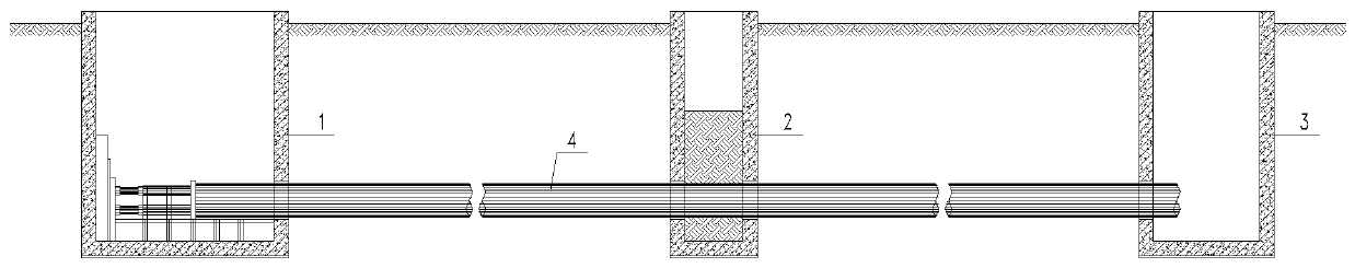
[0019] A pipe jacking construction method, comprising the steps of:

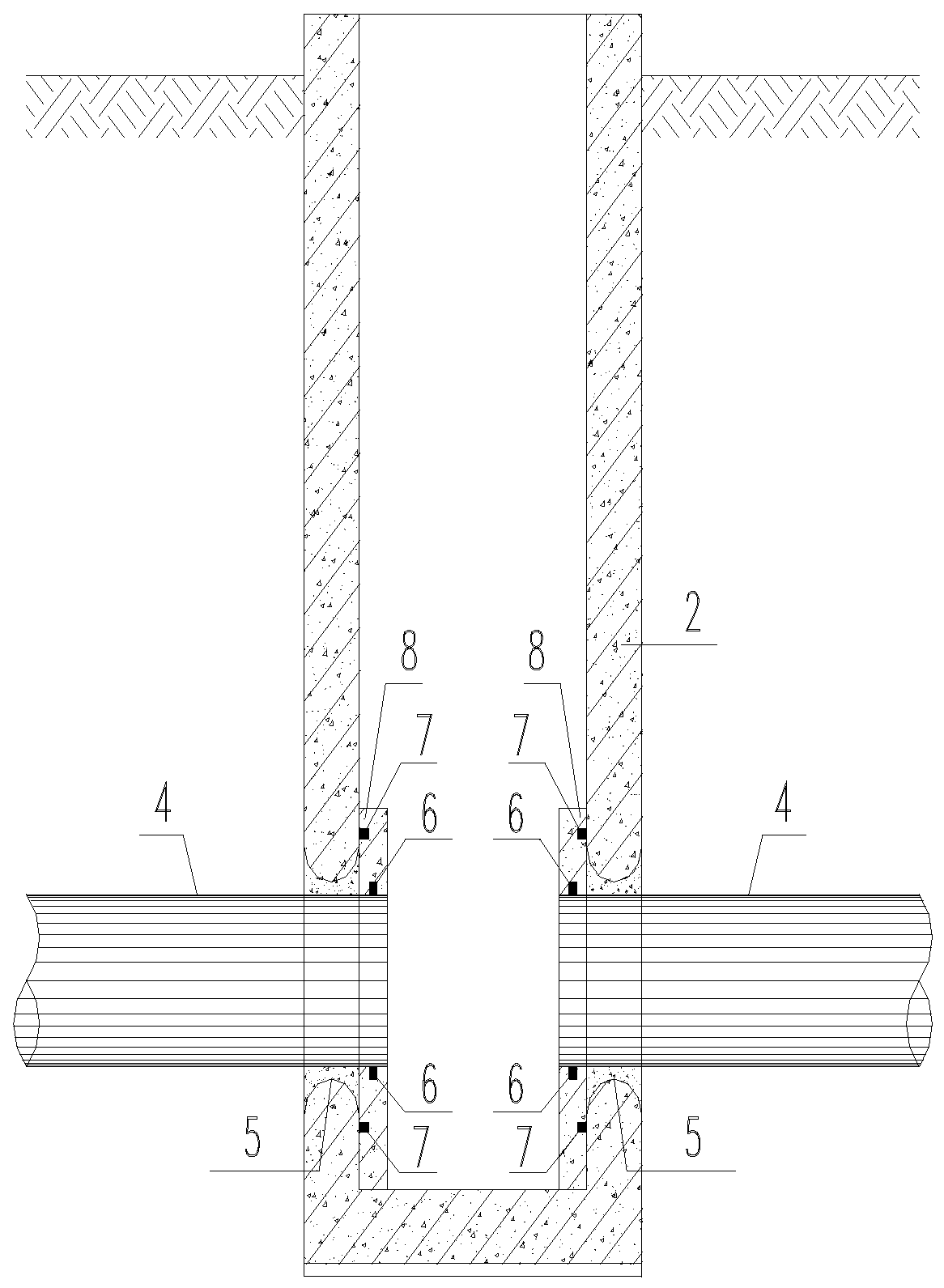
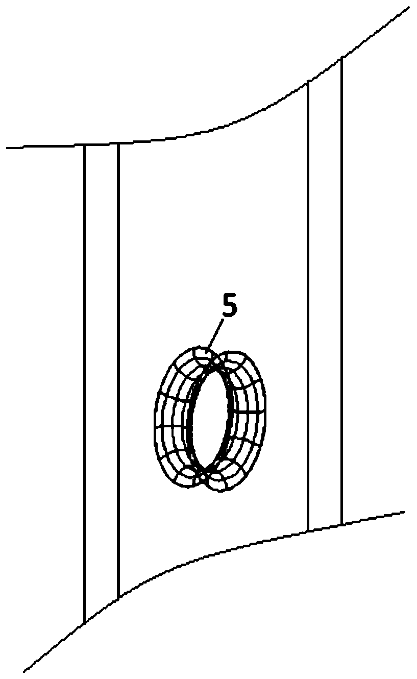
[0020] S1. According to the center line of the design pipeline, release the position of the excavation line at the selected construction position. According to the position and direction of the excavation line, simultaneously construct the pipe jacking working well 1, the pipe jacking receiving well 3, and the pipe jacking working well 1, top pipe jacking well 1 The pipe jacking well 2 between the pipe receiving wells 3; wherein, when constructing the pipe jacking well 2, holes 5 are reserved at the corresponding positions where the pipe passes through the wall plate in the pipe jacking well 2, and then the pipe jacking Compact and backfill the plain soil in the line-crossing well 2;

[0021] Preferably, the pipe jacking working well 1 and the pipe jacking receiving well 3 are all poured with reinforced concrete on the surrounding side walls, and a concrete bottom is laid at the bottom of the well and the re...


PUM


Abstract

The invention discloses a top pipe construction method, which comprises the following steps: S1, simultaneously constructing a top pipe working well, a top pipe receiving well and a top pipe line passing well, wherein in a process of constructing the top pipe line passing well, a hole is reserved in the part, corresponding to a top pipe crossing wall board, in the top pipe line passing well, and it conducts compressing and plain oil backfill; and S2, by virtue of top pipe ejecting equipment, making a top pipe directly pass through the top pipe line passing well and ejected into the top pipe receiving well in the top pipe working well, implementing grouting on the periphery of the top pipe; after completing top pipe construction, taking out the backfill oil and removing residual top pipe sections from the interior of the top pipe line passing well, and implementing water-proofing treatment on the reserved hole. The construction method provided by the invention has the advantages that the top pipe working well, the top pipe line passing well and the top pipe receiving well are simultaneously constructed, so that construction efficiency is improved; in addition, through the structuraldesign of the hole in the inner wall board of the top pipe line passing well, a larger fault-tolerant space is created for top pipe construction, so that the top pipe, which is slightly large, can slide into the inner circle of the hole along the outer round wall of the hole, and jamming can be prevented.

Description

technical field [0001] The invention relates to the construction technical field of drainage pipe jacking, in particular to a pipe jacking construction method. Background technique [0002] The scheme of pipeline design is compared and selected, considering factors such as pipeline burial depth, excavation conditions and economic efficiency, and pipe jacking construction is often used for pipelines with large burial depth and no excavation conditions. At present, my country's pipe jacking technology is becoming more and more mature. The single jacking length of pipe jacking with small and medium diameters (d800-d1200) generally exceeds 200m, and large-diameter and ultra-long-distance pipe jacking is also common. [0003] Considering the influence of factors such as dredging and branch pipe access for municipal drainage pipes, the national regulations limit the spacing of inspection wells for drainage pipes. See the table below for the maximum spacing between wells: [0004...

Claims


Application Information

Patent Timeline
Patent Type & Authority Patents(China)
IPC IPC(8): E03F3/06
CPCE03F3/06
Inventor 周兵李志南宋江刘尚春
Owner CENT & SOUTHERN CHINA MUNICIPAL ENG DESIGN & RES INST CO LTD
Why Eureka
Try Eureka