Method for arranging upper steel bars of laminated beam in penetrating mode

A technology of superimposed beams and steel bars, which is applied in the processing of building materials, construction, building construction, etc., can solve the problems of many solder joints of steel bars, a large number of upper steel bars 7, and large material loss, and achieve the goal of reducing equipment hoisting capacity Requirements, saving manpower and material resources and time, the effect of reducing the weight of a single piece

Inactive Publication Date: 2018-12-04
CHINA MCC20 GRP CORP
View PDF7 Cites 2 Cited by
  • Summary
  • Abstract
  • Description
  • Claims
  • Application Information

AI Technical Summary

Problems solved by technology

[0003] The overlapping joint 100 of the two ends of the stirrup 5 is located in the cast-in-place layer of the composite beam. After the cast-in-place layer of the composite beam is installed, the upper reinforcement 7 needs to be pierced in the stirrup 5 and the cast-in-place layer of the composite beam. The stirrups of the beam are relatively dense. The spacing of the stirrups is between 50mm and 150mm. The upper steel bar 7 is a stressed steel bar. The anchoring reinforcement reserved for cast-in-place column 1 also increases the difficulty of piercing the reinforcement. Usually, there are two methods when the upper reinforcement is not easy to wear. One is to cut the upper reinforcement into multiple sections, insert them in sections, and then weld them. It is to cut the stirrups and install the upper steel bars and then re-weld the cut stirrups and side bars. These two methods will cause too many solder joints of the steel bars, a large loss of materials, a large amount of waste of manpower, material resources and time, and are prone to accidents. Falling objects from high altitudes poses a high safety risk, thus delaying the construction period

Method used


Image

  • Method for arranging upper steel bars of laminated beam in penetrating mode
  • Method for arranging upper steel bars of laminated beam in penetrating mode
  • Method for arranging upper steel bars of laminated beam in penetrating mode

Examples


Embodiment Construction

[0023] In order to further explain the technical means and effects of the present invention to achieve the intended purpose of the invention, the specific implementation, structure, features and effects of the present invention will be described in detail below in conjunction with the accompanying drawings and preferred embodiments.

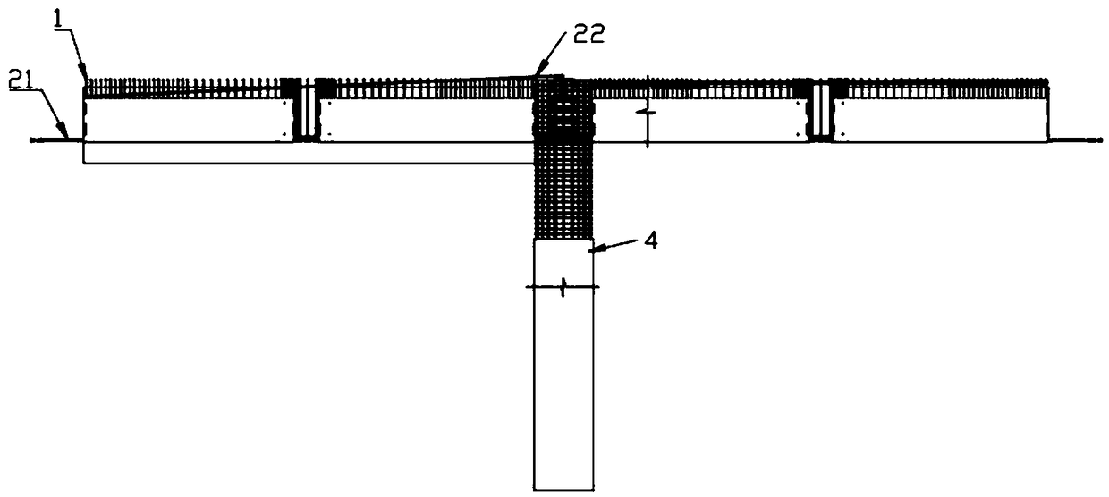
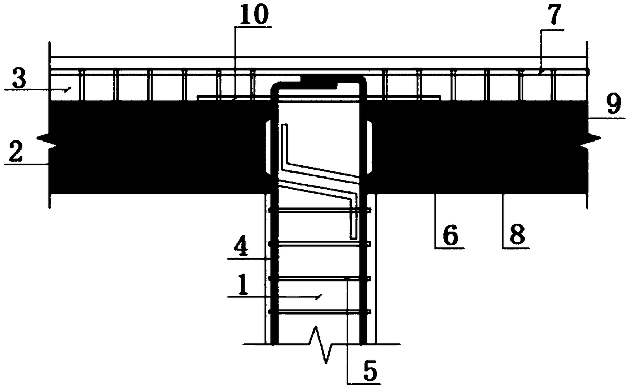
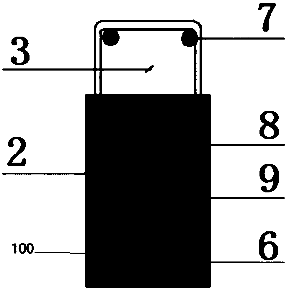
[0024] See image 3 , Figure 4 , the method for piercing the upper reinforcement of the composite beam according to the first embodiment of the present invention, comprising:

[0025] A. Install the stirrup 1 and the lower steel bar 21, and the prefabricated layer 3 of the laminated beam, wherein the lap joint of the two ends of the stirrup 1 near the end region 41 of the cast-in-place column 4 is located in the laminated beam prefabricated layer 3 Above the beam precast layer 3;

[0026] B. Install the prefabricated layer 3 of the laminated beam, open the overlapping joints of the two ends of the stirrup 1 in the end region 41, and form an op...


PUM


Abstract

The invention provides a method for arranging upper steel bars of a laminated beam in a penetrating mode. The method comprises the steps that A, stirrups and lower steel bars are installed, and a prefabricated layer of the laminated beam is constructed, wherein the positions, close to the overlapped places of both ends of the stirrups of an end portion area of a cast-in-situ column, of the prefabricated layer of the laminated beam are located on the upper part of the prefabricated layer of the laminated beam; B, the prefabricated layer of the laminated beam is installed, and the overlapped places of both ends of the stirrups of the end portion area are opened to form openings for allowing the upper steel bars to be placed; C, the upper steel bars are arranged in a penetrating mode; and D,both ends of the stirrups which are opened are overlapped. According to the method for arranging the upper steel bars of the laminated beam in a penetrating mode, the positions, close to the overlapped places of both ends of the stirrups of the end portion area of the cast-in-situ column, of the prefabricated layer of the laminated beam are located on the upper part of the prefabricated layer of the laminated beam, the overlapped places of both ends of the stirrups of the end portion area are opened after the prefabricated layer of the laminated beam is installed, and the upper steel bars canbe easily inserted into the stirrups, and therefore, the method for arranging the upper steel bars of the laminated beam in a penetrating mode can easily arrange the upper steel bars of the laminatedbeam in a penetrating mode.

Description

technical field [0001] The invention relates to the field of construction engineering, in particular to a method for piercing steel bars at the upper part of a composite beam. Background technique [0002] See figure 1 , figure 2 , the Chinese utility model patent whose authorization announcement number is CN207376646U discloses a kind of composite beam and cast-in-place column connecting node. The joint between the composite beam and the cast-in-place column includes a cast-in-place column 1 and composite beams connected on both sides of the upper end of the cast-in-place column 1, and the composite beam includes a composite beam prefabricated layer 2 and a The cast-in-place layer 3 of the composite beam, the first square stirrup 5 of the vertical reinforcement 4 and the vertical reinforcement 4 of the enclosing hoop are arranged in the cast-in-place column 1, and the prefabricated layer 2 of the composite beam on both sides is provided with along The steel bar 6 at the...

Claims


Application Information

Patent Timeline
Patent Type & Authority Applications(China)
IPC IPC(8): E04G21/12
CPCE04G21/12
Inventor 龙也谢非范作锋
Owner CHINA MCC20 GRP CORP
Why Eureka
Try Eureka