
Steam ejector

A technology of ejector and steam, applied in the field of ejector, can solve the problems of high consumption of high-pressure steam, low efficiency of pumping liquid, increase production cost, etc., and achieve the effects of high-efficiency pumping, simple structure and reduced consumption.

Pending Publication Date: 2018-12-04
闫韬
View PDF0 Cites 0 Cited by
  • Summary
  • Abstract
  • Description
  • Claims
  • Application Information

AI Technical Summary

Problems solved by technology

[0005] In the steam ejector provided by the prior art, since it is not easy to make the axis of the mixing diffuser coincide with the axis of the vapor-liquid outlet of the receiving chamber when the auxiliary pipe fitting welded with the mixing diffuser is welded to the receiving chamber, the nozzle The axis of the mixing diffuser is not easy to overlap, which makes the efficiency of pumping liquid low and the consumption of high-pressure steam is large
Moreover, since the mixing diffuser is welded to the receiving chamber through auxiliary pipe fittings, when the nozzle is transitionally matched with the receiving chamber or the flange, it is not easy to replace the mixing diffuser or the nozzle after it is damaged, which requires the replacement of the entire set of steam ejectors, increasing cost of production

Method used


Image

  • Steam ejector
  • Steam ejector
  • Steam ejector

Examples


Embodiment approach

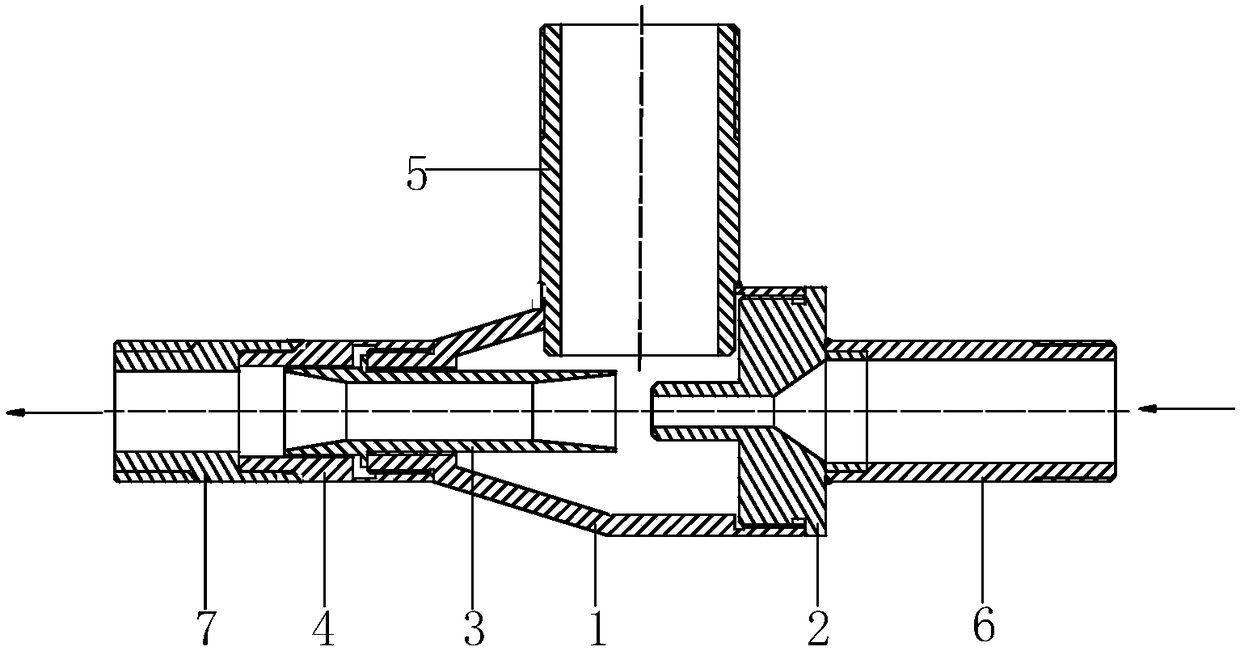
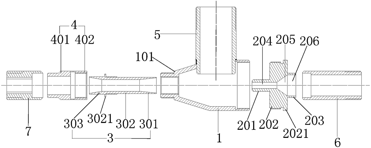
[0054] As a first embodiment: the nozzle 2 is screwed to the steam inlet; the mixing diffuser 3 is screwed to the vapor-liquid outlet.

[0055] The way of screw connection is easy to set up, which is convenient for the disassembly and assembly between the nozzle 2 and the receiving chamber 1 , and between the mixing diffuser pipe 3 and the receiving chamber 1 .

[0056] Specifically, internal threads are provided on the inner wall where the steam inlet and the vapor-liquid outlet of the receiving chamber 1 are located, and the outer walls of the nozzle 2 and the mixing diffuser 3 are provided with internal threads corresponding to the internal threads on the steam inlet and the vapor-liquid outlet. Cooperating external threads are used to facilitate the threaded connection of the nozzle 2, the mixing diffuser 3 and the receiving chamber 1.

[0057] After the nozzle 2, the mixing diffuser 3 are connected to the receiving chamber 1, in order to ensure that the axis of the nozzle...


PUM


Abstract

The invention discloses a steam ejector, and belongs to the field of ejectors. The steam ejector comprises a receiving chamber, a nozzle and a mixing diffuser pipe; a steam inlet, a liquid inlet and asteam-liquid outlet are formed in the receiving chamber, the axis of the steam inlet is overlapped with the axis of the steam-liquid outlet, and the liquid inlet communicates with a liquid conveyingpipeline; furthermore, the nozzle is detachably connected with the steam inlet, moreover, the output end of the nozzle extends into an inner cavity of the receiving chamber through the steam inlet, and the input end of the nozzle communicates with a steam conveying pipeline; and the mixing diffuser pipe is detachably connected with the steam-liquid outlet, and the input end of the mixing diffuserpipe extends into the inner cavity of the receiving chamber through the steam-liquid outlet. According to the steam ejector, the axis of the steam inlet of the receiving chamber is overlapped with theaxis of the steam-liquid outlet, the output end of the nozzle extends into the inner cavity of the receiving chamber through the steam inlet, the input end of the mixing diffuser pipe extends into the inner cavity of the receiving chamber through the steam-liquid outlet, so that the axis of the nozzle is overlapped with the axis of the mixing diffuser pipe, then a liquid can be sucked efficiently, and the liquid can be lifted by 3-10 meters through the steam ejector.

Description

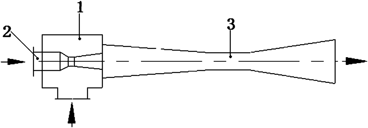
technical field [0001] The invention relates to the field of ejectors, in particular to a steam ejector. Background technique [0002] The steam ejector is a device powered by high-pressure steam that can pump water from a low water level to a high water level. It has the characteristics of simple structure, convenient maintenance, and energy saving. In petroleum, chemical and other industries, it is often necessary to pump liquid from a low water level to a high water level to complete production operations. Therefore, it is very necessary to provide a steam ejector used in industries such as petroleum and chemical industry. [0003] The prior art provides a steam ejector, as attached figure 1 As shown, the steam ejector includes: a receiving chamber 1 , a nozzle 2 , and a mixing diffuser 3 . Wherein, the receiving chamber 1 is provided with a steam inlet, a liquid inlet, and a vapor-liquid outlet. The axis of the steam inlet coincides with the axis of the vapor-liquid o...

Claims


Application Information

Patent Timeline
Patent Type & Authority Applications(China)
IPC IPC(8): F04F5/24F04F5/46
CPCF04F5/24F04F5/46
Inventor 闫韬闫高伦王礼梅张智
Owner 闫韬
Learn More