Jumper wire overheating shunting connection wire clamp
A technology of shunt connection and drainage clamp, which is applied in the direction of connection, conductive connection, electrical component connection, etc., to achieve the effect of quick operation, change of connection mode, and simple structure
- Summary
- Abstract
- Description
- Claims
- Application Information
AI Technical Summary
Problems solved by technology
Method used
Image
Examples
Embodiment 1
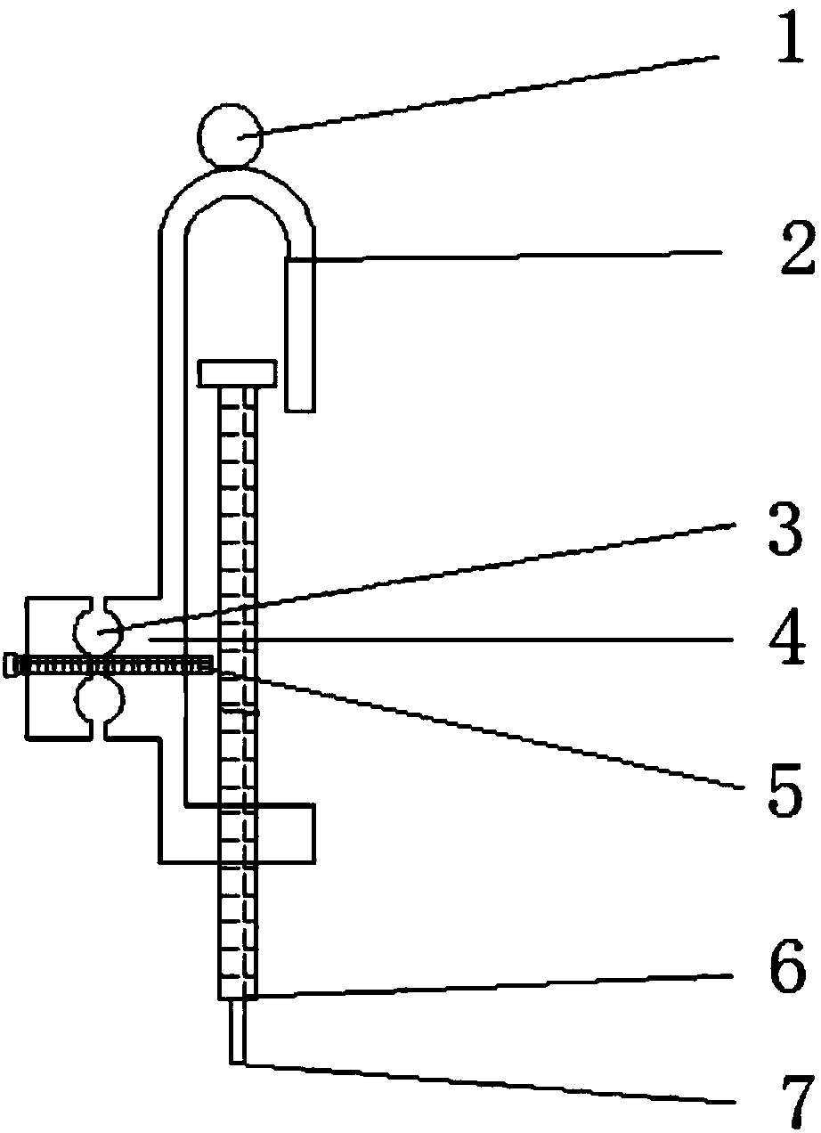
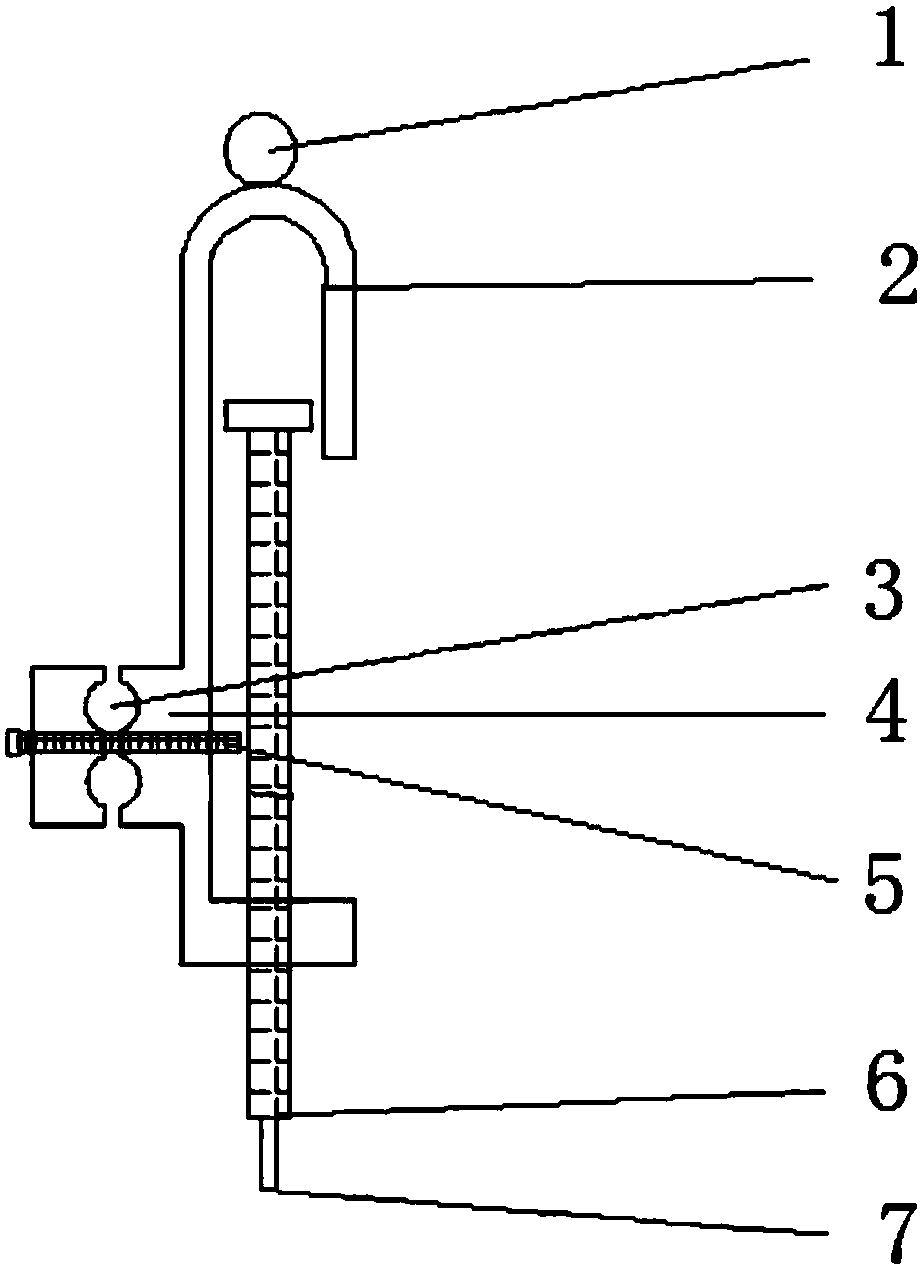
[0020] This embodiment provides a wire jumper overheating shunt connecting wire clip, which is characterized in that: the jumper wire overheating shunting connecting wire clip includes an upper operating ring 1, a drainage wire clip 2, a threading wire hole 3, and an adjustable backup wire Fixing device 4, spare lead fixing device bolt 5, fastening bolt 6, lower operating ring 7;
[0021] Among them: the upper operating ring 1 is fixedly connected to the upper part of the drainage wire clip 2, and the adjustable backup fixing device 4 is a split structure, which is arranged in the middle of the drainage wire clip 2. There are threading holes 3 between the split structures and pass through the backup wire The fixing device bolt 5 is locked, the fastening bolt 6 passes through the bottom of the drain wire clamp 2 and is parallel to the length direction of the drain wire clamp 2 , and the lower part of the drain wire clamp 2 has a lower operating ring 7 .
[0022] The upper opera...
Embodiment 2
[0029] This embodiment provides a wire jumper overheating shunt connecting wire clip, which is characterized in that: the jumper wire overheating shunting connecting wire clip includes an upper operating ring 1, a drainage wire clip 2, a threading wire hole 3, and an adjustable backup wire Fixing device 4, spare lead fixing device bolt 5, fastening bolt 6, lower operating ring 7;
[0030] Among them: the upper operating ring 1 is fixedly connected to the upper part of the drainage wire clip 2, and the adjustable backup fixing device 4 is a split structure, which is arranged in the middle of the drainage wire clip 2. There are threading holes 3 between the split structures and pass through the backup wire The fixing device bolt 5 is locked, the fastening bolt 6 passes through the bottom of the drain wire clamp 2 and is parallel to the length direction of the drain wire clamp 2 , and the lower part of the drain wire clamp 2 has a lower operating ring 7 .
[0031] The upper opera...
Embodiment 3
[0038] This embodiment provides a wire jumper overheating shunt connecting wire clip, which is characterized in that: the jumper wire overheating shunting connecting wire clip includes an upper operating ring 1, a drainage wire clip 2, a threading wire hole 3, and an adjustable backup wire Fixing device 4, spare lead fixing device bolt 5, fastening bolt 6, lower operating ring 7;
[0039] Among them: the upper operating ring 1 is fixedly connected to the upper part of the drainage wire clip 2, and the adjustable backup fixing device 4 is a split structure, which is arranged in the middle of the drainage wire clip 2. There are threading holes 3 between the split structures and pass through the backup wire The fixing device bolt 5 is locked, the fastening bolt 6 passes through the bottom of the drain wire clamp 2 and is parallel to the length direction of the drain wire clamp 2 , and the lower part of the drain wire clamp 2 has a lower operating ring 7 .
[0040] The drainage cl...
PUM
 Abstract
Description
Claims
Application Information
 - R&D
- Intellectual Property
- Life Sciences
- Materials
- Tech Scout
- Unparalleled Data Quality
- Higher Quality Content
- 60% Fewer Hallucinations
Browse by: Latest US Patents, China's latest patents, Technical Efficacy Thesaurus, Application Domain, Technology Topic, Popular Technical Reports.
© 2025 PatSnap. All rights reserved.Legal|Privacy policy|Modern Slavery Act Transparency Statement|Sitemap|About US| Contact US: help@patsnap.com


