Output voltage feedback circuit and temperature compensation circuit of switching converter

A temperature compensation circuit and switching converter technology, applied in the direction of output power conversion devices, electrical components, etc., can solve the problems of unsatisfied and variable voltage accuracy, and achieve a wide range of acquisition channels, stable voltage accuracy, and simple design principles Effect

Pending Publication Date: 2018-12-04
MORNSUN GUANGZHOU SCI & TECH
View PDF0 Cites 2 Cited by
  • Summary
  • Abstract
  • Description
  • Claims
  • Application Information

AI Technical Summary

Problems solved by technology

[0006] However, the existing technical solutions have the following problems in the design of the feedback loop using the Zener diode to stabilize the output voltage and provide the feedback current: Since the voltage stabilization value of the Zener diode changes with the change of the ambient temperature, it directly causes the product to be damaged in a high temperature environment. Compared with the output voltage of the product at normal temperature, the output voltage has a large change, and the voltage accuracy cannot be satisfied at all.

Method used


Image

  • Output voltage feedback circuit and temperature compensation circuit of switching converter
  • Output voltage feedback circuit and temperature compensation circuit of switching converter
  • Output voltage feedback circuit and temperature compensation circuit of switching converter

Examples


no. 1 example

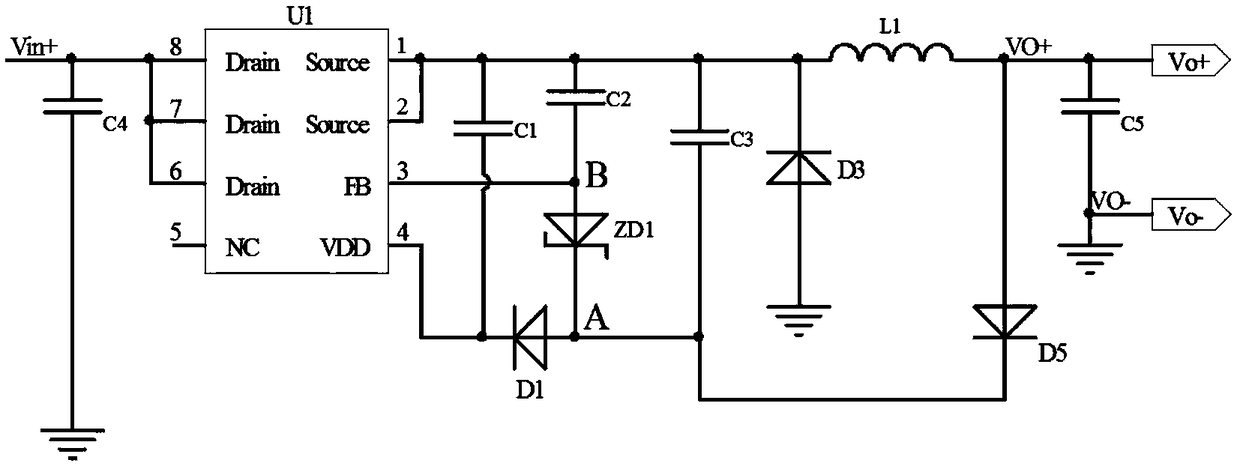
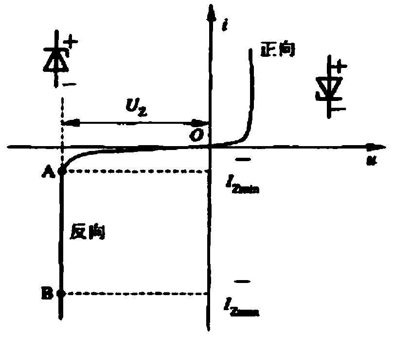
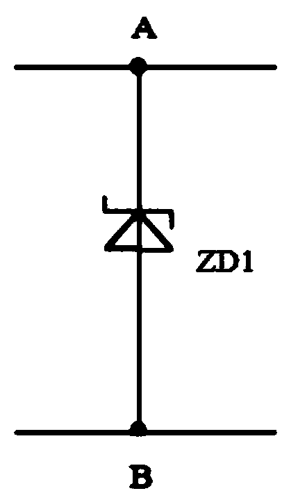
[0038] The temperature compensation circuit of the output voltage feedback circuit of Embodiment 1 of the present invention utilizes NTC resistors (also known as negative temperature coefficient thermistors) to perform temperature compensation on positive temperature characteristic regulator tubes, such as Figure 4 shown. The circuit connection method: Figure 4 Node C is connected to the common node of the resistor R11 and the NTC resistor, and the common node of the other end of the resistor R11 and the NTC resistor is connected to the cathode of the Zener diode ZD11, and then connected to the D node through the anode of the Zener diode ZD11. Will Figure 4 Circuit replacement between C and D nodes figure 1 The circuit between nodes A and B in the middle constitutes the overall solution of the embodiment of the present invention—an application of parallel NTC resistors in switching converters. The principle is to use the temperature characteristics of the thermistor to m...

no. 2 example

[0045] The temperature compensation circuit of the output voltage feedback circuit of Embodiment 2 of the present invention uses a PTC resistor (also called a thermistor with a positive temperature coefficient) to perform temperature compensation on a negative temperature characteristic voltage regulator tube, such as Figure 5 shown. The circuit connection mode of this embodiment: the Figure 5 Node E in the middle is connected to the common node of resistor R12 and PTC resistor, and the common node of the other end of resistor R12 and PTC resistor is connected to the cathode of Zener tube ZD12, and then connected to node F through the anode of Zener tube ZD12. Will Figure 5 Circuit replacement between E and F nodes figure 1 The circuit between the nodes A and B constitutes the overall circuit solution of the second embodiment where the parallel PTC resistors are applied to the switching converter. The principle of the embodiment is as follows: the Zener diode ZD12 with a...

no. 3 example

[0047] The third embodiment of the present invention is to use the negative temperature characteristic of the forward conduction voltage drop of the diode to perform temperature compensation for the voltage regulator tube, such as Figure 6 shown. The connection relation of the circuit: the node G is connected with the anode of the switch diode D6, the cathode of the diode D6 is connected with the cathode of the voltage regulator ZD13, and the anode of the voltage regulator ZD13 is connected with the node H. use Figure 6 Circuit replacement between nodes G and H in figure 1 The circuit structure between the nodes A and B is the overall circuit principle diagram of the third embodiment of the present invention applied to the switching converter. The principle of the third embodiment is as follows: since the forward working diode itself has a negative temperature characteristic, the conduction threshold voltage of the diode decreases when the temperature rises. Therefore, t...


PUM


Abstract

The invention provides an output voltage feedback circuit of a switching converter. The output voltage feedback circuit comprises a diode D5 and a Zener diode ZD1;an anode of the diode D5 is connectedwith a positive terminal of the output voltage, and an anode of the Zener diode ZD1 is used as an output end of the output voltage feedback circuit and is used to be connected with an FB pin of a control chip; a temperature compensation circuit is included; the temperature compensation circuit includes a compensation device complementary to the temperature variation characteristic of the Zener diode ZD1; and the temperature compensation circuit is serially connected between the diode D5 and the Zener diode ZD1, i.e., one end of the temperature compensation circuit is connected to a cathode ofthe diode D5, and the other end of the temperature compensation circuit is connected to a cathode of the Zener diode ZD1. Compared with the conventional voltage stabilization feedback circuits, the solution of the invention has more stable voltage precision in a high temperature environment.

Description

technical field [0001] The invention is applicable to the field of electronic circuit design of switching converters. Due to the influence of temperature, the stable voltage value of the voltage regulator tube changes at high temperature, resulting in the problem of drifting in the output voltage of the switching converter at high temperature. Aiming at this phenomenon, this solution proposes a temperature compensation circuit to improve the output voltage stability of the switching converter. Background technique [0002] At present, the development prospect of the power supply industry is rapidly developing in the direction of smaller size, higher integration and lower cost. Facing the background that the market puts forward higher technical requirements for volume and integration, using integrated IC as the main control chip has gradually become the mainstream solution for designing products. [0003] Highly integrated IC chips simplify peripheral circuits while bringin...

Claims


Application Information

Patent Timeline
IPC IPC(8): H02M1/00
CPCH02M1/00H02M1/0003
Inventor 金若愚王小亮梁宇正
Owner MORNSUN GUANGZHOU SCI & TECH
Why Eureka
Try Eureka