Composite compensation device for long-distance sparse power supply

A compensation device, long-distance technology, applied in circuit devices, reactive power compensation, harmonic reduction devices, etc., can solve the problems of complex compensation, high device cost, high-order harmonic amplification, etc.

Pending Publication Date: 2019-09-24
国网青海省电力公司果洛供电公司 +3
View PDF0 Cites 6 Cited by
  • Summary
  • Abstract
  • Description
  • Claims
  • Application Information

AI Technical Summary

Problems solved by technology

However, long-distance power supply will bring large line power loss and voltage drop. For example, when the line of the 10kV distribution network exceeds 200km, the line power loss is as high as 30% and the power supply voltage drops by more than 50%. In addition, the power grid in sparse areas There are many other challenges, such as power quality problems: the power consumption along the route is mainly non-industrial loads, the distribution of personnel and the difference in power consumption lead to three-phase imbalance, and the variety of electrical equipment leads to increased harmonics and reduced power factor, etc.
However, these devices have their own defects and cannot be applied to improve the power quality of long-distance transmission lines in the west
For example, the passive compensation device uses capacitors, inductors and other devices, and the device is relatively large; for example, the static var compensator can be adjusted

Method used


Image

  • Composite compensation device for long-distance sparse power supply
  • Composite compensation device for long-distance sparse power supply
  • Composite compensation device for long-distance sparse power supply

Examples


Embodiment Construction

[0054] In order to better illustrate the present invention and facilitate understanding of the technical solutions of the present invention, the present invention will be further described in detail below in conjunction with the accompanying drawings and specific embodiments. It should be understood that the following implementation examples are only used to illustrate the present invention, and do not represent or limit the protection scope of the present invention, and the protection scope of the present invention shall be determined by the claims.

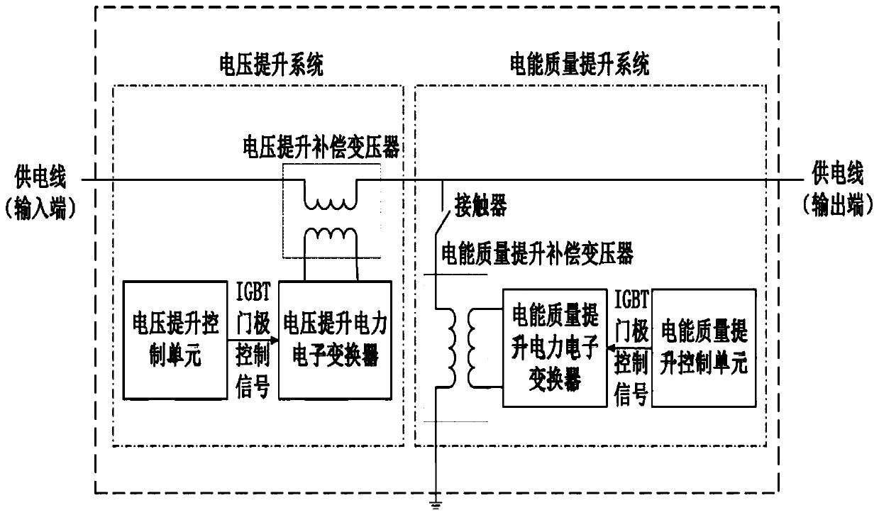
[0055] A compound compensation device for long-distance sparse power supply, its input is the input end of the power supply line, and its output is the output end of the power supply line, such as figure 1 As shown, including: voltage boosting system and power quality boosting system.

[0056]The voltage boosting system includes: a voltage boosting compensation transformer, a voltage boosting power electronic converter and a vol...


PUM


Abstract

The invention provides a composite compensation device for long-distance sparse power supply. The input is a power supply line input end, and the output is a power supply line output end. The device comprises a voltage boosting system and an electric energy quality boosting system, wherein the voltage boosting system comprises a voltage boosting compensation transformer, a voltage boosting power electronic converter and a voltage boosting control unit; and the electric energy quality boosting system comprises a contactor, an electric energy quality boosting compensation transformer, an electric energy quality boosting power electronic converter and an electric energy quality boosting control unit. According to the invention, the power electronic converter and the compensation transformer are used for injecting a current and a voltage into a power grid and performing real-time control, thereby achieving the comprehensive power quality improvement of power harmonic waves, power factors, three-phase imbalance compensation and the like and the voltage compensation function of a sparse power utilization area of a long power transmission line. The device has important significance on power supply radius extension, investment saving and power grid safety of the sparse power utilization area.

Description

technical field [0001] The invention belongs to a circuit device or system for power supply or distribution, in particular to a compensation device or system for an AC transmission line or an AC power distribution network. Background technique [0002] The western region of my country has a vast territory, low population density, and sparse power consumption. Using the traditional method to build new substations on the extended power supply lines requires a large construction investment and poor economic benefits. Therefore, it is necessary to consider extending the power supply radius to achieve long-distance power supply. However, long-distance power supply will bring large line power loss and voltage drop. For example, when the line of the 10kV distribution network exceeds 200km, the line power loss is as high as 30% and the power supply voltage drops by more than 50%. In addition, the power grid in sparse areas Technology, there are many other challenges, such as power q...

Claims


Application Information

Patent Timeline
IPC IPC(8): H02J3/12H02J3/01H02J3/18H02J3/26
CPCH02J3/12H02J3/01H02J3/1807H02J3/1878H02J3/26Y02E40/30Y02E40/40Y02E40/50
Inventor 陈文君徐国卿范越杨森林李永斌马丽山李沛然于涛董顺虎向大为张国瑞谭协初刘雨丁元杰段宏川马泽隆郭晓靖
Owner 国网青海省电力公司果洛供电公司
Why Eureka
Try Eureka