
Spinal injury emergency external fixator

An external fixator and spinal injury technology, applied in fractures, medical science, etc., can solve problems such as cumbersome operation, delay in treatment time, and patient damage, and achieve the effect of improving applicability

Active Publication Date: 2020-06-26
HENAN PROVINCE HOSPITAL OF TCM THE SECOND AFFILIATED HOSPITAL OF HENAN UNIV OF TCM
View PDF10 Cites 0 Cited by
  • Summary
  • Abstract
  • Description
  • Claims
  • Application Information

AI Technical Summary

Problems solved by technology

This not only makes the operation cumbersome and delays the precious treatment time, but also there are still hidden dangers. You still need to be careful when moving and transporting, because the patient's spine has been damaged. Secondary damage will cause further damage to the patient. When the patient is lifted onto the flat panel, the patient is usually tightened with a bandage and then fixed on the flat panel. Although this can fix the patient on the flat panel, due to the elasticity of the bandage Larger, the medical staff will inevitably bump during the process of transporting the patient. At this time, the patient's body will rise and fall with the flat plate, which will cause further damage to the patient's injured spine. Fixed to the flat plate, at this time, the patient’s body can be better fastened and will not be displaced vertically relative to the flat plate due to bumps, but it also brings problems. The device with a harder material will clamp the patient’s abdomen tightly. It causes the patient's breathing to be unsmooth, affects the patient's normal breathing, and brings further damage to the patient. Therefore, a spinal injury emergency external fixator that can limit the patient's body vertically without affecting its normal breathing is particularly important.

Method used


Image

  • Spinal injury emergency external fixator
  • Spinal injury emergency external fixator
  • Spinal injury emergency external fixator

Examples


Embodiment 1

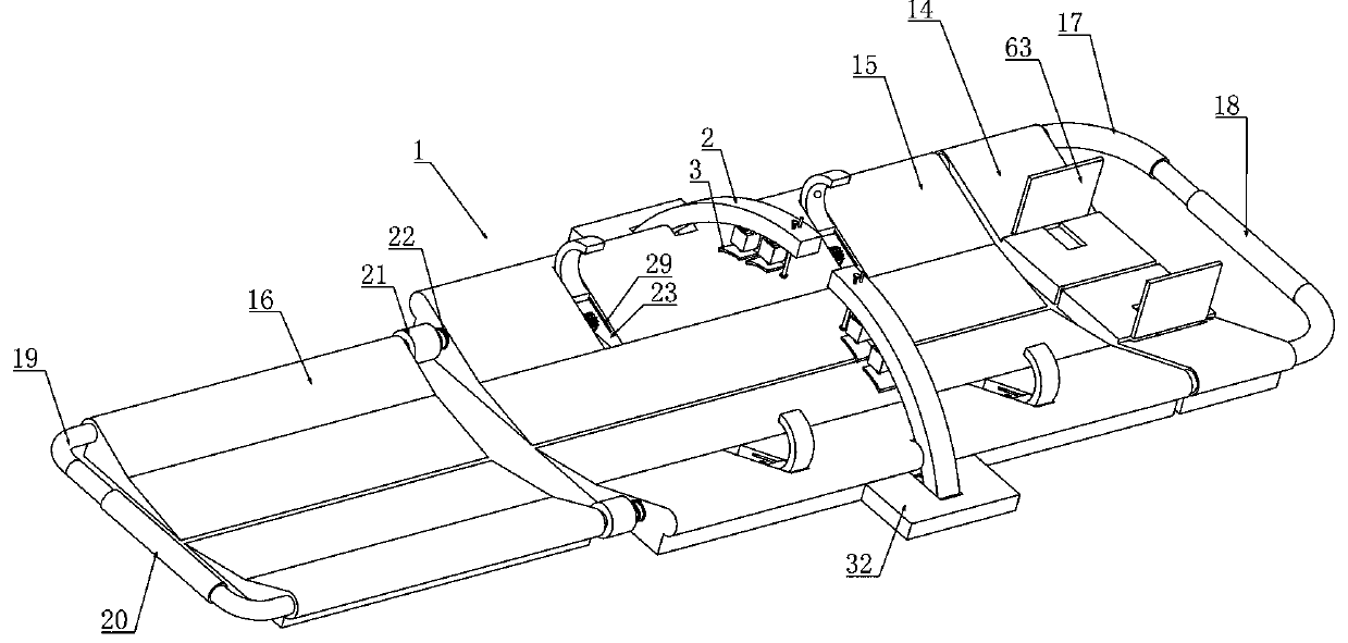
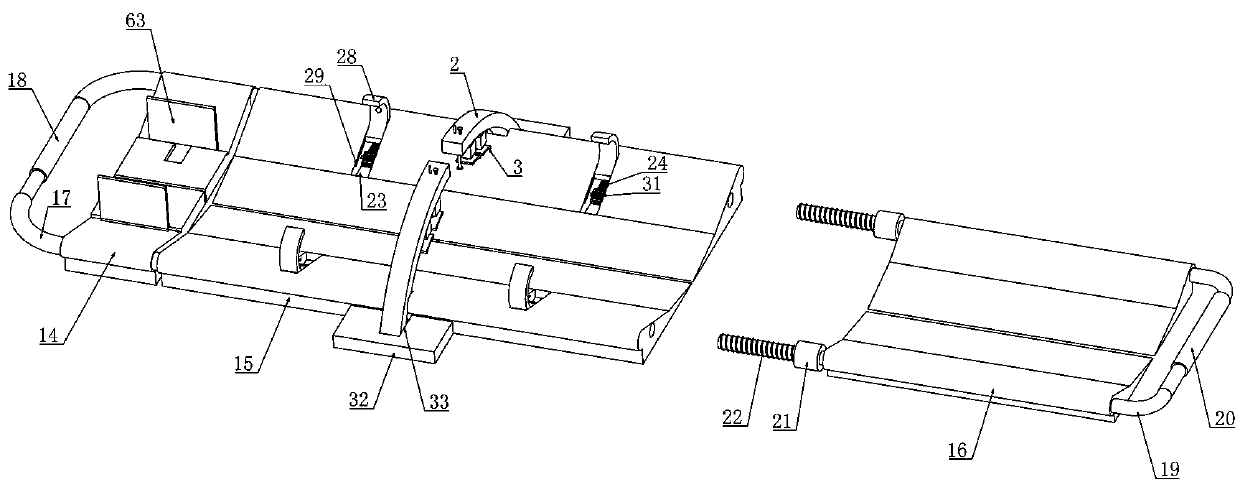
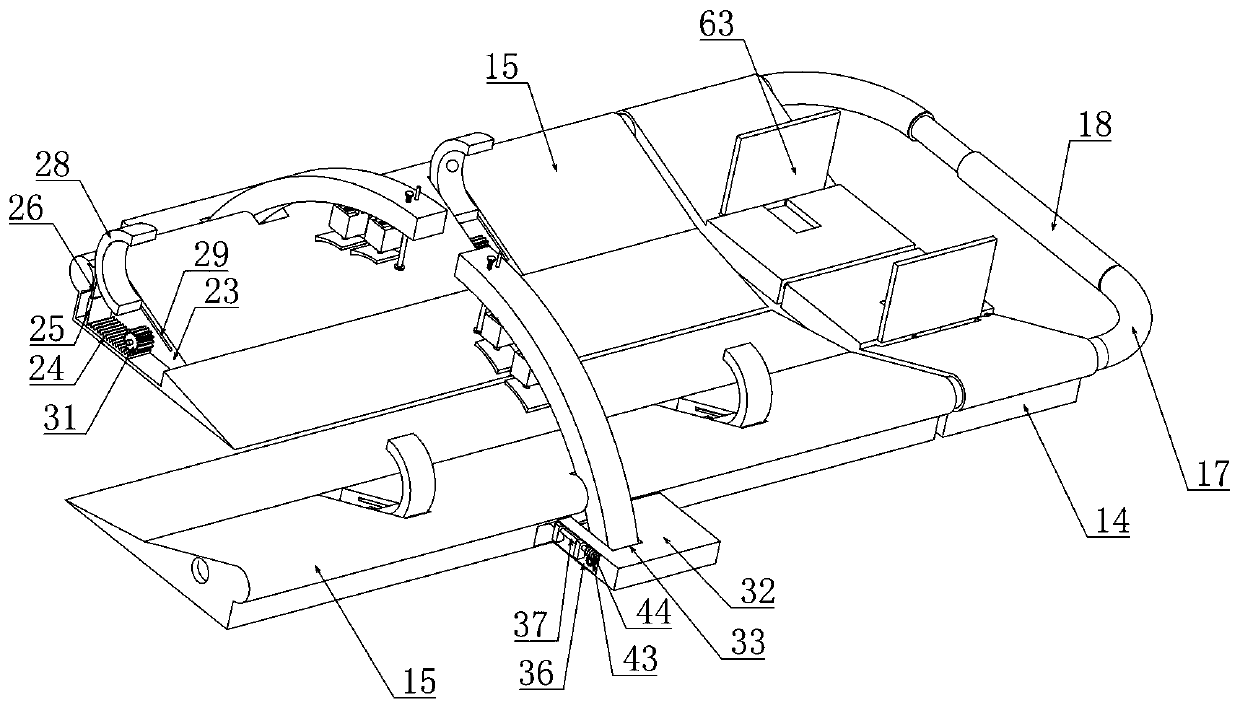
[0039] Embodiment 1, the first aid external fixation frame for spinal injuries, including a frame body 1, is characterized in that, the upper and lower lateral sides of the frame body 1 are respectively provided with left and right clamping devices at longitudinal intervals, and are located between the two left and right clamping devices on the same side There is a first elastic arc-shaped plate 2 that is rotatably connected to the upper lateral side of the frame body 1. The lower end of the first elastic arc-shaped plate 2 is fixedly connected with a plurality of damping devices, and the lower end of the damping device is connected with a second elastic arc-shaped plate. 3. The first elastic arc-shaped plate 2, the damping device and the second elastic arc-shaped plate 3 form a vertical clamping device, and the left and right clamping devices and the vertical clamping device on the same side pass through the first transmission mechanism and the vertical clamping device respecti...

Embodiment 2

[0041] Embodiment 2. On the basis of Embodiment 1, the damping device includes a plurality of first rectangular tubes 5 fixedly connected to the lower end of the first elastic arc-shaped plate 2 and open at both ends of the upper and lower ends. A piston rod 6 is slidingly fitted, and the lower end of the piston rod 6 is connected with a second elastic arc-shaped plate 3, and the upper end surface of the first rectangular cylinder 5 is connected with a first thin plate 7 in rotation between the longitudinal side walls on both sides of the horizontal direction. The opposite side walls of the two first thin plates 7 are slidably fitted with a second thin plate 8 and the opposite side walls of the two second thin plates 8 are threaded with a first screw 9, and the first screw 9 is rotatably connected to the first On the thin plate 7, a rectangular groove 10 with an open lower end is provided in the middle of the opposite side walls of the two first thin plates 7, and a longitudina...

Embodiment 3

[0043] Embodiment 3, on the basis of Embodiment 1, the frame body 1 includes a head support plate 14, a waist support plate 15, and a leg support plate 16 arranged symmetrically left and right, and the support portion of the waist support plate 15 is in the shape of The lumbar support plate 15 arranged symmetrically on a beveled plane cooperates with each other to form a groove shape with high sides and a low center. On the first L-shaped bar 17 that side wall direction extends and two first L-shaped bars 17 are placed between the head support plate 14 and the waist support plate 15 external parts and are connected with the first electric telescopic link 18, two described legs The upper support plates 16 are respectively sleeved on the second L-shaped rods 19 extending perpendicular to the longitudinal side wall of the leg support plates 16, and the ends of the two second L-shaped rods 19 are away from the head support plate 14 through the second electric telescopic The rods 2...


PUM


Abstract

The invention relates to a first-aid external fixing frame for spine injury. The problem that a traditional spine fixing frame cannot synchronously better limit a patient body to a frame body and makethe patient normally breathe is effectively solved. According to the first-aid external fixing frame, left and right clamping devices are longitudinally arranged on the two transverse sides of the frame body at an interval, a first elastic arc plate rotatably connected to one transverse side of the frame body is arranged between the left and right clamping devices on the same side, and the lowerend of the first elastic arc plate is fixedly connected with a plurality of damping devices; the lower ends of the damping devices are connected with a second elastic arc plate, the first elastic arcplate, the damping devices and the second elastic arc plate form a vertical clamping device, and the left and right clamping devices can better limit the patient at the horizontal position; the vertical clamping device can better limit the patient body at the vertical position and cannot influence the breath of the patient, so that the patient body can be stably located on the fixing frame.

Description

technical field [0001] The invention relates to a first-aid fixation device for spinal cord injuries, which belongs to the technical field of orthopedics and traumatology medical equipment, and in particular to a first-aid external fixator for spinal cord injuries. Background technique [0002] Human limb injuries often occur, especially in mines, construction sites and traffic accident-prone areas. After the injury occurs, it must be sent to the hospital for treatment in time. For those with serious injuries, for example, patients with limb injuries accompanied by fractures and blood loss, it is necessary to take temporary measures at the accident scene to stop the bleeding urgently, fix the limbs with appropriate measures, and then transport them to be safer. If not handled properly, it will increase the degree of injury to the patient. For the transport of patients with cervical spine, a transport board is generally used. The so-called transport board is actually a stret...

Claims


Application Information

Patent Timeline
Patent Type & Authority Patents(China)
IPC IPC(8): A61F5/05
CPCA61F5/05
Inventor 和艳红
Owner HENAN PROVINCE HOSPITAL OF TCM THE SECOND AFFILIATED HOSPITAL OF HENAN UNIV OF TCM
Learn More