Storage box for micro sample injector and method of use
A micro-sampler and storage box technology, applied to chemical instruments and methods, supporting appliances, laboratory appliances, etc., can solve problems such as blockage, slow natural volatilization speed, and easy contamination of needles, and achieve simple and fast connection methods. Evaporation speed and hygienic effect
- Summary
- Abstract
- Description
- Claims
- Application Information
AI Technical Summary
Problems solved by technology
Method used
Image
Examples
Embodiment 1
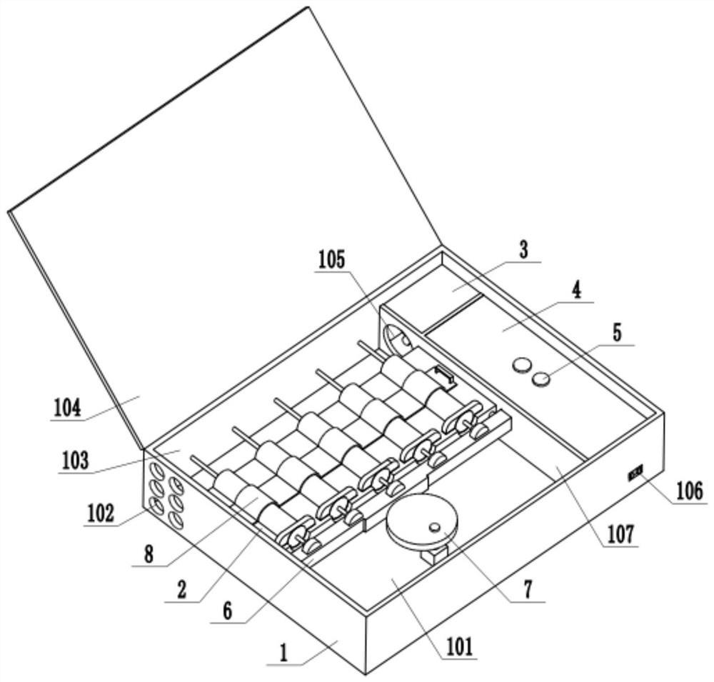
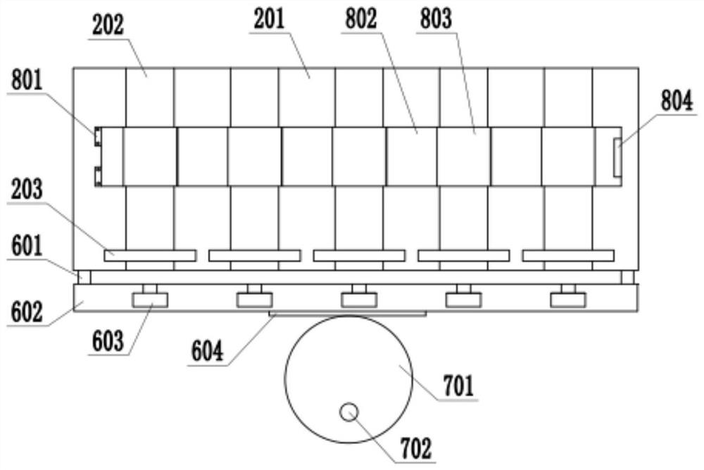
[0039] Such as Figure 1-3 As shown, a micro sampler storage box includes a box body 1, a box cover 104 is provided on one side of the upper end of the box body 1, a partition 107 is provided in the box body 1, and a partition 107 of the partition 107 is provided. One side is provided with a fixing device 2, and the two sides of the fixing device 2 are respectively a front vacant area 101 and a rear vacant area 103. The front vacant area 101 is provided with a power device 7, and the rear vacant area 103 is convenient for placement of needles. A traction device 6 is provided between the fixing device 2 and the power device 7, and the traction device 6 is connected with the power device 7 and the fixing device 2 respectively. Charging port 106, charging port 106 is electrically connected with battery 4, and battery 4 is charged directly, has avoided the loaded down with trivial details of dismantling battery 4, has increased convenience of use; Fan 3 is located at the side near...
Embodiment 2
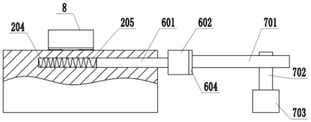
[0045] Such as Figure 4-6 As shown, the traction device 6 includes a connecting rod 601 and a drawing rod 602, one end of the connecting rod 601 is vertically connected with the drawing rod 602, and the other end of the connecting rod 601 is arranged in the connecting groove 204, and the length of the connecting groove 204 can be The reciprocating movement of the connecting rod 601 is ensured.
[0046] Described power unit 7 comprises motor two 704, driving rod 706, driving connecting rod 709, and described motor two 704 is arranged on the middle part of front vacant area 101, and motor two 704 is provided with two output shafts 705, each output shaft The end of 705 is provided with incomplete gear 708, and the quantity of described driving connecting rod 709 is two, is respectively arranged at the two ends of drawing rod 602, and one end of every driving connecting rod 7079 is all connected with a driving rod 706, The middle part of the driving rod 706 is provided with a ba...
PUM
 Abstract
Description
Claims
Application Information
 - R&D
- Intellectual Property
- Life Sciences
- Materials
- Tech Scout
- Unparalleled Data Quality
- Higher Quality Content
- 60% Fewer Hallucinations
Browse by: Latest US Patents, China's latest patents, Technical Efficacy Thesaurus, Application Domain, Technology Topic, Popular Technical Reports.
© 2025 PatSnap. All rights reserved.Legal|Privacy policy|Modern Slavery Act Transparency Statement|Sitemap|About US| Contact US: help@patsnap.com


