Coating equipment and film coating abnormality detecting method
A kind of coating equipment and coating technology, which is applied to the device and coating of the surface coating liquid, which can solve the problems of inability to achieve the improvement effect, sprinkler streaks, time-consuming and labor-intensive problems, etc.
Active Publication Date: 2018-12-07
HKC CORP LTD +1
7 Cites 0 Cited by
AI-Extracted Technical Summary
Problems solved by technology
This operation is time-consuming and laborious, and may not achi...
Method used
In this way, by controlling the liquid outlet units distributed at intervals, the preset solution can be coated in the sub-coating areas distributed at intervals to form alternate light and dark stripes, so that the abnormal liquid outlet units of the spraying state can be found in time, which is quick and easy Accurately determine which liquid outlet unit is abnormal in the spraying state.
In this way, by setting the widths of each sub-coating area 1011 corresponding to the same liquid outlet unit to be equal, the corresponding relationship between the sub-coating area 1011 and the different liquid outlet positions of the same liquid outlet unit can be simplified. When the film is abnormal, the specific liquid outlet position where the abnormal spraying state occurs in the liquid outlet unit where the spraying state is abnormal can be determined more quickly and accurately.
Like this, by arranging each liquid outlet unit to correspond to a plurality of sub-coating areas 1011; The width of the pattern formed by the coating of a single liquid outlet unit 20 is equal to the sum of the widths of each sub-coating area corresponding to it, can make Simultaneous coating of each liquid outlet unit can form a complete coating pattern on the surface of the substrate 10 to be coated; at the same time, when the coating film is abnormal, the position of the sub-coating area 1011 corresponding to the nozzle stripe and the position of the sub-coating area 1011 The corresponding relationship with the liquid outlet unit can quickly and accurately determine which liquid outlet unit has an abnormal spraying state, and can quickly and accurately determine the specific liquid outlet location where the abnormal spraying state of the liquid outlet unit has an abnormal spraying state.
Wherein, the second identific...
Abstract
The invention discloses coating equipment and a film coating abnormality detecting method. The coating equipment comprises a substrate to be coated and multiple liquid outlet units; the substrate to be coated comprises a coating area; the coating area comprises multiple coating subareas; all the coating subareas are arranged in a first direction in sequence; each coating subarea corresponds to a first identifying code; the first identifying codes respectively correspond to the coating subareas; each first identifying code corresponds to one liquid outlet unit; and the liquid outlet units are used for coating preset solution in the corresponding coating subareas. In the coating equipment, as the first identifying codes respectively correspond to the coating subareas, and each first identifying code corresponds to one liquid outlet unit, each coating subarea can correspond to one unique liquid outlet unit. When the film coating is abnormal, the abnormal coating state of the specific liquid outlet unit can be quickly and accurately determined according to the correspondence between the coating subareas and the liquid outlet units.
Application Domain
Liquid surface applicatorsCoatings
Technology Topic
Film coatingFilm-coated tablet +1
Image
Examples
- Experimental program(1)
Example Embodiment
[0049] In order to make the purpose, technical solutions and advantages of the present invention clearer, the technical solutions of the present invention will be clearly and completely described through implementation with reference to the accompanying drawings in the embodiments of the present invention. Obviously, the described embodiments are the embodiment of the present invention. Some, but not all, embodiments. Based on the embodiments of the present invention, all other embodiments obtained by persons of ordinary skill in the art without making creative efforts belong to the protection scope of the present invention.
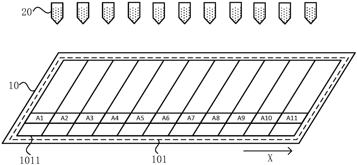
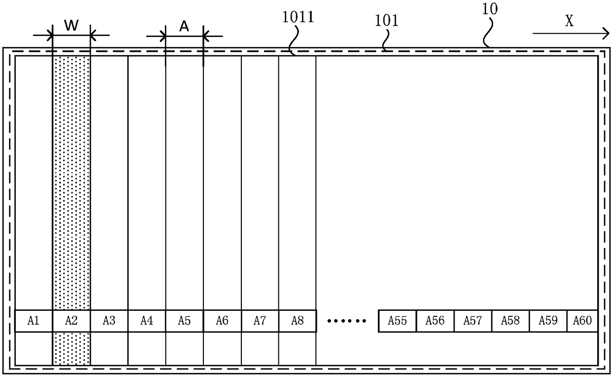
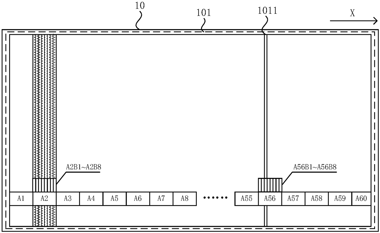
[0050] figure 1 It is a schematic structural diagram of a coating equipment provided by an embodiment of the present invention. refer to figure 1 , the coating equipment includes: a substrate to be coated 10 and a plurality of liquid outlet units 20; the substrate to be coated 10 includes a coating area 101, and the coating area 101 includes a plurality of sub-coating areas 1011, each sub-coating area 1011 along The first direction X is arranged sequentially; each sub-coating area 1011 corresponds to a first identification code An (the value of n can be an integer equal to or greater than 1, figure 1 exemplarily shown in A1-A11), the first identification code An corresponds to the sub-coating area 1011, and each first identification code An corresponds to a liquid outlet unit 20; the liquid outlet unit 20 is used to The solution is applied to the corresponding sub-coating area 1011.
[0051]Wherein, the substrate to be coated 10 includes various substrates that can be coated with a thin film. Exemplarily, the substrate 10 to be coated may be a rigid substrate such as a glass substrate or a silicon substrate, or may be a flexible substrate such as a stainless steel substrate or a polyimide substrate, or may be any of the above-mentioned substrates on which some functional film layers have been formed on the surface. Rigid substrate or flexible substrate. Those skilled in the art can understand that, according to the difference of prepared products, substrates 10 to be coated with different materials can be selected. Obviously, the materials of substrates 10 to be coated include but are not limited to the above-mentioned substrate materials, and any material that can be used as a substrate can be used. Falling into the protection scope of the present invention, the embodiment of the present invention does not limit the material of the substrate 10 to be coated.
[0052] Wherein, the preset solution can be contained in the liquid outlet unit 20 ( figure 1 Shown in), or the liquid outlet unit 20 and the parts containing the pre-set solution ( figure 1 Not shown in ) communicated through the intermediate pipe. Under the action of gravity and/or pressure, the preset solution flows or sprays out from the liquid outlet unit 20 , and is coated into the sub-coating area 1011 of the substrate 10 to be coated.
[0053] Exemplarily, when the coating equipment is a spray coating device, the liquid outlet unit 20 may be a spray head of the spray coating device.
[0054] It should be noted, figure 1 It only exemplarily shows that the cross-sectional shape of the liquid outlet unit 20 is a pentagon, which is only an exemplary illustration, rather than a limitation to the liquid outlet unit 20 provided by the embodiment of the present invention. In other embodiments, the three-dimensional shape of the liquid outlet unit 20 can be set according to the actual requirements of the coating equipment, which is not limited in the embodiment of the present invention.
[0055] Wherein, the coating area 101 is an area where a preset solution needs to be coated.
[0056] Exemplary, figure 1 It is shown that the coating area 101 is located at the center of the substrate to be coated 10, and the substrate to be coated 10 also includes a non-coating area surrounding the coating area 101, which is only an exemplary illustration, not a limitation. In other embodiments, the position of the coating area 10 on the substrate 10 to be coated and the relative position of the coating area 10 to the non-coating area can also be set according to the actual needs of the coating equipment and/or the substrate 10 to be coated. Positional relationship.
[0057] Exemplary, figure 1 The coating area 101 shown in the figure includes 11 sub-coating areas 1011, and each sub-coating area corresponds to a first identification code An. Along the first direction X, the sub-coating areas 1011 are arranged sequentially, and the corresponding first identification codes An are: A1, A2, A3, A4, A5, A6, A7, A8, A9, A10, A11. at the same time, figure 1 A plurality of liquid outlet units 20 are shown in , and each first identification code An corresponds to only one liquid outlet unit 20 . Therefore, each sub-coating area 1011 corresponds to only one liquid outlet unit 20 .
[0058] It should be noted, figure 1 It only exemplarily shows that the number of sub-coating areas 1011 is 11, and the number of liquid outlet units 20 is 11, that is, the number of sub-coating areas 1011 and the liquid outlet units 20 are in one-to-one correspondence, which is only exemplary. description, not limitation. In other embodiments, the number of sub-coating areas 1011 and the number of liquid outlet units 20 can be set according to the actual needs of the coating equipment; meanwhile, each liquid outlet unit 20 can correspond to one sub-coating area 1011, or One liquid outlet unit 20 corresponds to multiple sub-coating areas 1011, which is not limited in this embodiment of the present invention.
[0059] Furthermore, it should be noted that, figure 1 It only exemplarily shows that the liquid outlet unit 20 is located above the substrate 10 to be coated, and the first direction X is a direction parallel to one side of the substrate 10 to be coated, which are only exemplary illustrations, and It is not limited to the coating equipment provided in the embodiment of the present invention. In other embodiments, the relative positional relationship between the liquid outlet unit 20 and the substrate 10 to be coated in space, and the distance between the first direction X and the side of the substrate 10 to be coated can be set according to the actual needs of the coating equipment. The size of the angle is not limited in this embodiment of the present invention.
[0060] The coating equipment provided by the embodiment of the present invention includes a coating area 10 by setting the substrate 10 to be coated, and the coating area 10 includes a plurality of sub-coating areas 1011, and each sub-coating area 1011 is arranged in sequence along the first direction X; Each sub-coating area 1011 corresponds to a first identification code An, the first identification code An corresponds to the sub-coating area, and each first identification code An corresponds to a unique liquid outlet unit 20 . Thus, each sub-coating area 1011 corresponds to a unique liquid outlet unit 20 . Therefore, when the coating film is abnormal, by distinguishing which sub-coating area 1011 the nozzle stripe is located in, and according to the corresponding relationship between the above-mentioned sub-coating area 1011 and the liquid outlet unit 20, the liquid outlet unit 20 that has an abnormal spraying state can be quickly and accurately determined Which one specifically.
[0061] In another embodiment, figure 2 It is a schematic structural diagram of a substrate to be coated of a coating device provided by an embodiment of the present invention. refer to figure 1 and figure 2 , the sub-coating area 1011 is set corresponding to the liquid outlet unit 20; the width W of the pattern formed by the liquid outlet unit 20 is equal to the width A of the corresponding sub-coating area 1011.
[0062] Wherein, the liquid outlet unit 20 can be arranged along a direction parallel to a side direction of the substrate 10 to be coated, and when the liquid outlet unit 20 and the substrate 10 to be coated move relatively, the liquid outlet unit 20 can coat the substrate to be coated 10 corresponding to the sub-coating area 1011.
[0063] Exemplarily, the liquid outlet unit 20 can be arranged along the first direction X, when the liquid outlet unit 20 moves along the direction perpendicular to the first direction X, and/or, the substrate to be coated moves along the direction perpendicular to the first direction X , the liquid outlet unit 20 forms a coating pattern in each sub-coating area 1011 of the substrate 10 to be coated.
[0064] By setting the sub-coating areas 1011 in one-to-one correspondence with the liquid outlet units 20, and the width W of the pattern formed by coating the liquid outlet unit 20 is equal to the width of the corresponding sub-coating area 1011, each liquid outlet unit 20 can be Simultaneous coating can form a complete coating pattern on the surface of the substrate 10 to be coated; at the same time, when the coating film is abnormal, by distinguishing which sub-coating area 1011 the nozzle stripe is located in, and according to the sub-coating area 1011 and the liquid outlet unit 20 one-to-one correspondence, quickly and accurately determine which liquid outlet unit 20 is abnormal in the spraying state.
[0065] It should be noted, figure 2 It only exemplarily shows that the number of sub-coating areas 1011 is 60, that is, the number of the corresponding first identification code An (wherein, the value of n is a positive integer from 1 to 60) is 60, which is only Illustrated by way of example, not limitation. In other implementation manners, the number of the sub-coating areas 1011 and the corresponding first identification codes An can be set according to actual requirements of the coating equipment, which is not limited in this embodiment of the present invention.
[0066] In yet another embodiment, image 3 It is a schematic structural diagram of a substrate to be coated in another coating device provided by an embodiment of the present invention. refer to image 3 , each liquid outlet unit corresponds to a plurality of sub-coating areas 1011; the width of a pattern formed by coating a single liquid outlet unit 20 is equal to the sum of the widths of the corresponding sub-coating areas.
[0067] Wherein, different sub-coating areas 1011 corresponding to the same liquid outlet unit respectively correspond to different liquid outlet positions of the liquid outlet unit.
[0068] Exemplary, image 3 The first identification code corresponding to each sub-coating area 1011 is grouped, and the group of each group of first identification code is shown by Am (wherein, the value of m is a positive integer from 1 to 60), and each group of first identification code Each of the identification codes Am includes 8 first identification codes AmBh (wherein, the value of m is a positive integer ranging from 1 to 60, and the value of h is a positive integer ranging from 1 to 8). Exemplarily, the second group A2 includes 8 first identification codes A2B1 to A2B8, and these 8 first identification codes respectively correspond to different liquid outlet positions of the same liquid outlet unit. Similarly, the 56th group A56 includes 8 first identification codes A56B1-A56B8, and these 8 first identification codes can correspond to different liquid outlet positions of another liquid outlet unit. Similarly, the other groups of first identification codes correspond to different positions of the corresponding liquid outlet units.
[0069] When the coating film is abnormal, according to the position of the sub-coating area 1011 corresponding to the nozzle stripe, the first identification code AmBh corresponding to the position of the sub-coating area 1011, and the difference between the first identification code AmBh and the different positions of the liquid outlet unit Corresponding relationship, quickly and accurately determine which liquid outlet unit with abnormal spraying state is, and quickly and accurately determine the specific liquid outlet position where the liquid outlet unit with abnormal spraying state has abnormal spraying state.
[0070] It should be noted, image 3 It only exemplarily shows that the number of sub-coating areas 1011 is 480, which can be divided into 60 groups, each group has 8, that is, each liquid outlet unit corresponds to 8 sub-coating areas, which is only exemplary It is intended to illustrate rather than limit the coating equipment provided in the embodiments of the present invention. In other embodiments, the number of sub-coating areas corresponding to each liquid outlet unit can be set according to the actual needs of the coating equipment, and the number of sub-coating areas corresponding to different liquid outlet units can be the same or different , which is not limited in this embodiment of the present invention.
[0071] Exemplary, Figure 4 It is a schematic diagram of the corresponding relationship between the width of the pattern formed by coating and the width of the sub-coating area provided by the embodiment of the present invention. refer to Figure 4 , the number of sub-coating areas 1011 in this group is 10, and the width of each sub-coating area 1011 is not equal, wherein, the width of the first 9 sub-coating areas 1011 is A', and the width of the 10th sub-coating area 1011 is B', the width of the pattern formed by coating the liquid outlet unit is W. Wherein, the width W of the pattern formed by the coating of the liquid outlet unit is equal to the sum of the widths of the sub-coating areas 1011 in the group, that is, W=A'*9+B'.
[0072] Exemplarily, the value of A' may be 10mm, the value of B' may be 15mm, and at this time, the value of W is 105mm. Or, the value of A' can be 10mm, the value of B' can be 5mm, and at this time, the value of W is 95mm. This is only an exemplary description, not a limitation.
[0073] It should be noted, Figure 4 It only exemplarily shows that the number of sub-coating areas 1011 in this group is 10, and the width of the last sub-coating area 1011 is greater than the width of other sub-coating areas 1011, which is only an exemplary description, rather than limited. In other embodiments, the number of sub-coating areas 1011 in each group and the width of each sub-coating area 1011 can be set according to the actual requirements of the coating equipment, which is not limited in this embodiment of the present invention.
[0074] In this way, by setting each liquid outlet unit to correspond to a plurality of sub-coating areas 1011; the width of the pattern formed by the coating of a single liquid outlet unit 20 is equal to the sum of the widths of the corresponding sub-coating areas, so that each liquid outlet Simultaneous coating of the units can form a complete coating pattern on the surface of the substrate 10 to be coated; at the same time, when the coating film is abnormal, it can The corresponding relationship of the units can quickly and accurately determine which liquid outlet unit is abnormal in the spraying state, and can quickly and accurately determine the specific liquid outlet position of the abnormal spraying state of the liquid outlet unit.
[0075] In yet another embodiment, Figure 5 It is a schematic diagram of the corresponding relationship between the width of another pattern formed by coating and the width of the sub-coating area provided by the embodiment of the present invention. refer to Figure 5 , the widths of each sub-coating area 1011 corresponding to the same liquid outlet unit are equal.
[0076]Exemplarily, the number of sub-coating areas 1011 in this group is 10, and the width of each sub-coating area 1011 is equal, as shown by A, and the width of the pattern formed by the coating of the liquid outlet unit is W, then W=A* 10.
[0077] Exemplarily, the value of A may be 10mm, and the value of W is 100mm. This is only an exemplary description, not a limitation.
[0078] It should be noted, Figure 5 It is only exemplarily shown that the number of sub-coating areas 1011 in a group is 10, which is only an exemplary description, not a limitation.
[0079] In this way, by setting the widths of each sub-coating area 1011 corresponding to the same liquid outlet unit to be equal, the corresponding relationship between the sub-coating area 1011 and different liquid outlet positions of the same liquid outlet unit can be simplified. , can more quickly and accurately determine the specific liquid outlet position where the abnormal spraying state occurs in the liquid outlet unit where the abnormal spraying state occurs.
[0080] Furthermore, it should be noted that, Figure 4 and Figure 5 1 and 2 only exemplarily show that the area to be coated is the third sub-coating area 1011 along the first direction X in the group, which is only an exemplary description, not a limitation.
[0081] In yet another embodiment, Image 6 It is a structural schematic diagram of another coating equipment provided by the embodiment of the present invention. refer to Image 6 , the coating device may further include a control unit 30; the control unit 30 is connected to the liquid outlet unit 20, and is used to control whether each liquid outlet unit 20 performs a coating operation.
[0082] Wherein, the control unit 30 can control each liquid outlet unit 20 to perform coating operation independently.
[0083] Exemplarily, a parameter list is stored in the control unit 30 , and the parameter list includes spraying parameters related to the spraying state of the liquid outlet unit 20 . Exemplarily, by setting the parameters in the parameter list, the corresponding liquid outlet unit 20 can be controlled to perform the coating operation or not to perform the coating operation.
[0084] Exemplarily, the above-mentioned control unit 30 can also control the liquid outlet unit 20 through a button switch, a switch displayed on the operation interface, or directly changing parameters in the control program, and the embodiment of the present invention does not limit the way to realize the control.
[0085] By setting the control unit 30 to control whether each liquid outlet unit 20 performs the coating operation, it is possible to set the liquid outlet unit 20 that needs to perform the coating operation according to different coating requirements, thereby realizing flexible control of the coating equipment.
[0086] In yet another embodiment, the working process of the coating equipment includes a coating process; during the coating process, the control unit 30 controls each odd-numbered liquid outlet unit 20 to perform coating operations at the same time; or, during the coating process, the control unit 30 controls The unit 30 controls each even-numbered liquid outlet unit 20 to perform the coating operation at the same time.
[0087] Exemplary, Figure 7 It is a schematic diagram of the distribution of patterns formed by coating by a coating equipment provided in an embodiment of the present invention. refer to Figure 7 , corresponding to the one-to-one correspondence between the sub-coating areas 1011 and the liquid outlet units. When the even-numbered liquid outlet units perform the coating operation at the same time, the formation is as follows: Figure 7 The coating pattern shown is that a coating pattern is formed in each even-numbered sub-coating area. Exemplarily, a coating pattern is formed in each sub-coating area 1011 corresponding to an even number of n in the first identification code An (wherein, the value of n is a positive integer from 1 to 60), so that a spacer can be formed Distributed elongated coating pattern.
[0088] Exemplary, Figure 8 It is a schematic diagram of the distribution of patterns formed by coating with another coating equipment provided in the embodiment of the present invention. refer to Figure 8 , corresponding to the one-to-one correspondence between the sub-coating areas 1011 and the liquid outlet units. It is also possible to form a coating pattern in each sub-coating area 1011 corresponding to the first identification code (wherein, the value of n is a positive integer from 1 to 60) in which the value of n is a multiple of 3, so that a spacer can be formed Distributed elongated coating pattern. At this time, the width of the interval between adjacent coating patterns is equal to twice the width of the elongated coating pattern.
[0089] It should be noted, Figure 7 and Figure 8 It only exemplarily shows that when the value of n corresponding to the first identification code An (wherein, the value of n is a positive integer from 1 to 60) is an even number or a multiple of 3, the substrate 10 to be coated Coating patterns formed in each sub-coating area 1011. This is only an exemplary description, not a limitation. In other implementation manners, the position of the liquid outlet unit performing the coating operation can be set according to the actual requirements of the coating equipment, which is not limited in this embodiment of the present invention.
[0090] In this way, by controlling the liquid outlet units distributed at intervals and coating the preset solution in the sub-coating areas distributed at intervals, light and dark stripes can be formed, so that the liquid outlet units with abnormal spraying status can be found in time, and quickly and accurately determined Which is the specific liquid outlet unit that has an abnormal spraying state?
[0091] In yet another embodiment, continue to refer to Image 6 , the coating device can also include an adjustment unit 40, the adjustment unit 40 is electrically connected to the liquid outlet unit 20; the adjustment unit 40 is used to adjust the coating parameters of the liquid outlet unit 20, so that the preset solution coated by the liquid outlet unit 20 A preset threshold is met; wherein, the coating parameter 20 includes a voltage value.
[0092] Wherein, the coating effect of the pattern formed by coating can be changed by adjusting the voltage value of the liquid outlet unit 20 .
[0093] Exemplarily, the coating of a polyimide (polyimide, PI) film on a glass substrate is taken as an example for description. The thickness of the PI film can be determined according to the brightness and darkness of the PI film on the glass substrate. If the PI film in a certain sub-coating area 1011 is bright, it indicates that the thickness of the PI film in the sub-coating area 1011 is relatively thin. Increasing the voltage value of the liquid outlet unit 20 corresponding to the sub-coating area 1011 increases the thickness of the PI film in the sub-coating area 1011; if the PI film in a certain sub-coating area 1011 is dark, it indicates that the sub-coating area The thickness of the PI film in the sub-coating zone 1011 is relatively thick, and the thickness of the PI film in the sub-coating zone 1011 can be reduced by lowering the voltage value of the liquid outlet unit 20 corresponding to the sub-coating zone 1011.
[0094] Therefore, after determining the specific location of the liquid outlet unit 20 where the abnormality occurs, the adjustment unit 40 can be used to adjust the coating parameters of the liquid outlet unit 20 to improve the abnormal situation, so that the abnormal situation of the coating film can be improved conveniently and quickly.
[0095] It should be noted that, the above is only described by coating a PI film on a glass substrate, and detecting whether an abnormality of the coating film occurs through the lightness and darkness of the PI film as an example, not limiting. In other embodiments, the material of the substrate to be coated, the material of the coated film and the detection method used in the abnormal detection method of the coating can be set according to the actual needs of the coating equipment, which is not limited in the embodiment of the present invention .
[0096] It should be noted, Image 6 It only exemplarily shows that the control unit 30 and the adjustment unit 40 control the liquid outlet unit 20 independently, which is only an exemplary description, not a limitation. In other implementation manners, there may also be signal transmission between the control unit 30 and the adjustment unit 40, and the two cooperate to control the liquid outlet unit 20, which is not limited in this embodiment of the present invention.
[0097] Furthermore, it should be noted that, Figure 1-Figure 8 It only exemplarily shows that the sub-coating area 1011 is in the shape of a strip, which is only an exemplary description, not a limitation. In other embodiments, the shape of the sub-coating area 1011 can be set according to the actual requirements of the coating equipment, which is not limited in the embodiment of the present invention. Figure 1-Figure 3 , Figure 6-Figure 8 It only exemplarily shows that the shape of the substrate 10 to be coated is a rectangle, which is only an exemplary description, not a limitation. In other implementation manners, the shape of the substrate 10 to be coated can be set according to actual requirements, which is not limited in the embodiment of the present invention.
[0098] In yet another embodiment, each liquid outlet unit corresponds to a second identification code; the second identification code is in one-to-one correspondence with the liquid outlet unit; the adjusting unit is used to adjust the The coating parameters of the liquid outlet unit, so that the preset solution coated by the liquid outlet unit meets the preset threshold.
[0099] Exemplarily, both the first identification code and the second identification code can be added to the parameter list of the control unit. At this time, when editing the parameter list, the substrate to be coated and the coating area (each sub-coating area) therein can be scaled down by a certain factor and added to the parameter list, and corresponding to each sub-coating area, Add the first identification code corresponding to it; at the same time, the liquid outlet unit and its spatial distribution can be scaled down by a certain factor and added to the parameter list, and corresponding to each liquid outlet unit, add the second identification code corresponding to it.
[0100] Wherein, the second identification code corresponds to the liquid outlet unit one by one, and the first identification code corresponds to the sub-coating area one by one. Since the second identification code corresponds to one or more sub-coating areas, the second identification code corresponds to one or more sub-coating areas. Corresponding to multiple first identification codes, based on the corresponding relationship between the second identification code and the first identification code, by adjusting the coating parameters of the liquid outlet unit so that the preset solution meets the preset threshold, the corresponding value can be adjusted or improved. The condition of the coating film in the sub-coating area can detect and improve the abnormality of the coating film, and the detection and improvement process can be controlled based on digitization (the correspondence between the second identification code and the first identification code), the control process is simple, and the response speed is fast , by setting the coating abnormality detection unit and cooperating with the adjustment unit, the self-feedback detection and adjustment process of the coating equipment can be realized, thereby realizing automatic control.
[0101] Based on the same inventive concept, an embodiment of the present invention also provides a coating abnormality detection method. The coating film abnormality detection method can be applied to the coating equipment provided in the above embodiment. For details not explained in detail in the method, reference may be made to the explanation of the coating equipment in the above-mentioned embodiment, and details are not repeated here.
[0102] Exemplary, Figure 9 It is a schematic flow chart of a coating film abnormality detection method provided by an embodiment of the present invention. refer to Figure 9 , the method includes:
[0103] S01. The liquid outlet unit applies the preset solution required for film formation to one side of the substrate to be coated.
[0104] Can refer to figure 1 , the liquid outlet unit 20 applies the preset solution to one side of the substrate 10 to be coated.
[0105] Wherein, the substrate 10 to be coated includes a coating area 101, and the coating area 101 includes a plurality of sub-coating areas 1011, and each sub-coating area 1011 is arranged sequentially along the first direction X; each sub-coating area 1011 corresponds to a first The value of an identification code An(n can be an integer equal to or greater than 1, figure 1 exemplarily shown as A1-A11), the first identification code An corresponds to the sub-coating area 1011 respectively, and each first identification code An corresponds to a liquid outlet unit 20 .
[0106] S02. According to the corresponding relationship between the sub-coating area and the first identification code, and the corresponding relationship between the first identification code and the liquid outlet unit, determine the position of the abnormal liquid outlet unit.
[0107] which, combined with figure 1 Each sub-coating area 1011 corresponds to a first identification code An, the first identification code An corresponds to the sub-coating area, and each first identification code An corresponds to a liquid outlet unit 20 . Thus, each sub-coating area 1011 corresponds to a unique liquid outlet unit 20 . Therefore, when the coating film is abnormal, according to the corresponding relationship between the sub-coating area 1011 and the liquid outlet unit 20, the specific location of the abnormal liquid outlet unit 20 can be quickly and accurately determined.
[0108]The coating abnormality detection method provided by the embodiment of the present invention is applied to the coating equipment provided in the above-mentioned embodiment. The coating equipment includes a coating substrate and a plurality of liquid outlet units. It includes a plurality of sub-coating areas, each sub-coating area is arranged in sequence along the first direction; each sub-coating area corresponds to a first identification code, and the first identification code corresponds to the sub-coating area respectively, and each first The identification code corresponds to a unique liquid outlet unit. Thus, each sub-coating area corresponds to a unique liquid outlet unit. Therefore, when the coating film is abnormal, by distinguishing which sub-coating area the nozzle stripe is located in, and according to the corresponding relationship between the above-mentioned sub-coating area and the liquid outlet unit, it is possible to quickly and accurately determine which liquid outlet unit has the abnormal spraying state. . It solves the problem in the prior art that when determining which liquid outlet unit is abnormal in the spraying state, the operation is time-consuming and laborious and the judgment is inaccurate.
[0109] Note that the above are only preferred embodiments of the present invention and applied technical principles. Those skilled in the art will understand that the present invention is not limited to the specific embodiments described here, and various obvious changes, readjustments, mutual combinations and substitutions can be made by those skilled in the art without departing from the protection scope of the present invention. Therefore, although the present invention has been described in detail through the above embodiments, the present invention is not limited to the above embodiments, and can also include more other equivalent embodiments without departing from the concept of the present invention, and the present invention The scope is determined by the scope of the appended claims.
PUM


Description & Claims & Application Information
We can also present the details of the Description, Claims and Application information to help users get a comprehensive understanding of the technical details of the patent, such as background art, summary of invention, brief description of drawings, description of embodiments, and other original content. On the other hand, users can also determine the specific scope of protection of the technology through the list of claims; as well as understand the changes in the life cycle of the technology with the presentation of the patent timeline. Login to view more.