LLC synchronous rectifying device and control method, electronic device and storage medium thereof

A synchronous rectification and device control technology, which is applied in the fields of electronic equipment, LLC synchronous rectification devices, and storage media, can solve problems such as troublesome turn-off time of secondary MOSFET, unfavorable efficiency, MOSFET damage, etc., and achieve fast turn-off time and accurate turn-off time. Off-time, easy to control effects

Active Publication Date: 2018-10-16
南昌沃尔贯新能源科技有限公司
View PDF3 Cites 6 Cited by
  • Summary
  • Abstract
  • Description
  • Claims
  • Application Information

AI Technical Summary

Problems solved by technology

However, when outputting low voltage and high current, the rectification loss accounts for a considerable proportion of the total loss due to the increase in the forward conduction voltage drop of the secondary diode of the LLC resonant converter, which is not conducive to the improvement of efficiency.
At present, most of the existing LLC synchronous rectification devices use a dedicated control chip, and it is difficult to set the circuit parameters. The circuit parameters may cause damage to the MOSFET of the synchronous rectification during the debugging process. In addition, there are pure software control synchronization On-off of the rectifier MOSFET, but when the switching frequency is less than the resonant frequency (fs<fr), it is difficult to determine the turn-off time of the secondary MOSFET, so it is troublesome to calculate the turn-off time of the secondary MOSFET by software

Method used


Image

  • LLC synchronous rectifying device and control method, electronic device and storage medium thereof
  • LLC synchronous rectifying device and control method, electronic device and storage medium thereof
  • LLC synchronous rectifying device and control method, electronic device and storage medium thereof

Examples


Embodiment Construction

[0025] In order to make the purpose, technical solution and advantages of the present invention clearer, the present invention will be further described in detail below in conjunction with the accompanying drawings and embodiments. It should be understood that the specific embodiments described here are only used to explain the present invention, not to limit the present invention.

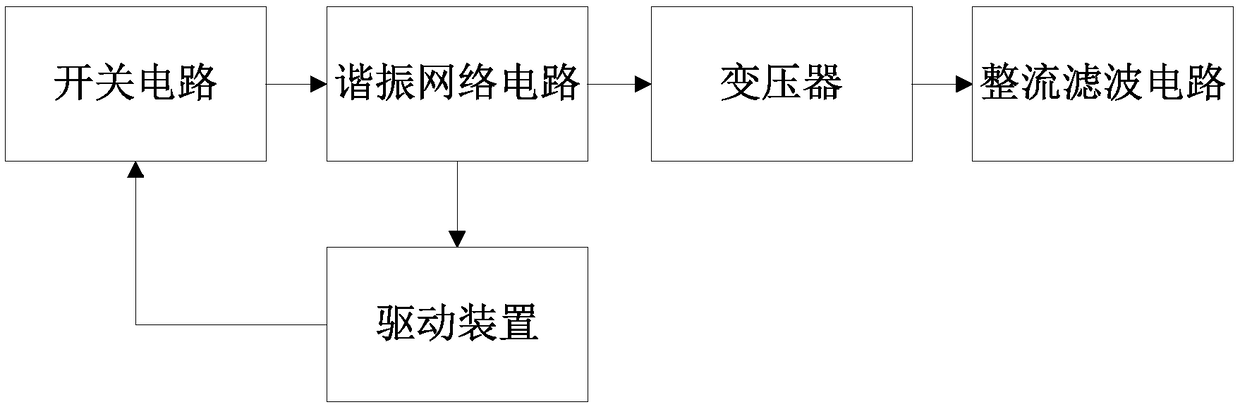
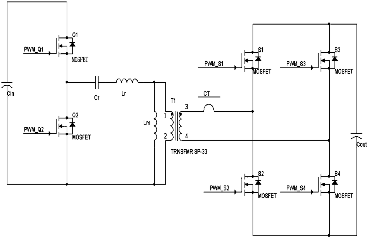
[0026] LLC synchronous rectification devices, such as Figure 1-Figure 2 As shown, it includes input terminal, switching circuit, resonant network circuit, transformer, rectification and filtering circuit, output terminal, and also includes a drive device, which includes a drive module, a resonant frequency detection module, an excitation current measurement module, a rectification shutdown module, and a drive The module is connected to the switch circuit, the drive module outputs a driving signal to drive the switch circuit to conduct, the resonant frequency detection module and the excitation cu...


PUM


Abstract

The invention provides an LLC synchronous rectifying device. The LLC synchronous rectifying device comprises an input end, a switching circuit, a resonant network circuit, a transformer, a rectifyingand filtering circuit, an output end and a driving device, the driving device comprises a driving module, a resonant frequency detecting module, an excitation current detecting module, and a rectification shutdown module, the driving module is connected to the switching circuit, the driving module outputs the driving signals to drive the switching circuit to be turned on, the resonant frequency detecting module and the excitation current detecting module are respectively connected with the resonant network circuit, and the resonant frequency detecting module acquires the resonant current of the resonant network circuit, and resonant frequency detecting module sends the resonant current to the rectification shutdown module, the excitation current detecting module obtains the excitation current of the resonant network circuit, and sends the excitation current to the rectification shutdown module, and the rectification shutdown module receives the resonant current and the excitation current, and monitors the corresponding time of driving signal when the resonant current and excitation are equal. The LLC synchronous rectifying device can effectively, quickly and accurately determine the turn-off time of the secondary MOSFET and the control is simple and the cost is low.

Description

technical field [0001] The invention relates to the technical field of protection circuits, in particular to an LLC synchronous rectification device and a control method thereof, electronic equipment, and a storage medium. Background technique [0002] LLC resonant converters are widely used in the field of DC / DC converters because they can realize soft switching of power devices in the full load range. However, when outputting low voltage and high current, the rectification loss accounts for a considerable proportion of the total loss due to the increase in the forward conduction voltage drop of the secondary diode of the LLC resonant converter, which is not conducive to the improvement of efficiency. At present, most of the existing LLC synchronous rectification devices use a dedicated control chip, and it is difficult to set the circuit parameters. During the debugging process, the circuit parameters may cause damage to the MOSFET of the synchronous rectification. The on...

Claims


Application Information

Patent Timeline
IPC IPC(8): H02M3/335
CPCH02M3/33592Y02B70/10
Inventor 陈滨陈娟方波
Owner 南昌沃尔贯新能源科技有限公司
Why Eureka
Try Eureka