Metal sheet flanging equipment

A metal sheet and flanging technology, which is applied to metal processing equipment, feeding devices, positioning devices, etc., can solve the problems of high production cost and low production efficiency, and achieve low cost, high production cost, and metal flanging. Easy to process effect

Pending Publication Date: 2018-12-07
东莞市中腾自动化设备制造有限公司
View PDF0 Cites 1 Cited by
  • Summary
  • Abstract
  • Description
  • Claims
  • Application Information

AI Technical Summary

Problems solved by technology

At present, the metal stamping process is still used for the forming of some thinner and easier to form low-strength metal sheets, which will obviously lead to higher production costs and lower production efficiency

Method used


Image

  • Metal sheet flanging equipment
  • Metal sheet flanging equipment
  • Metal sheet flanging equipment

Examples


Embodiment 1

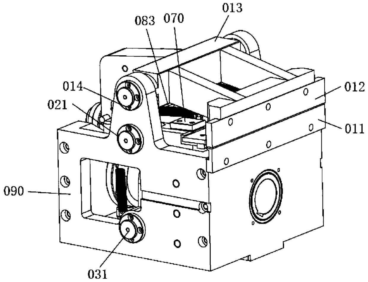
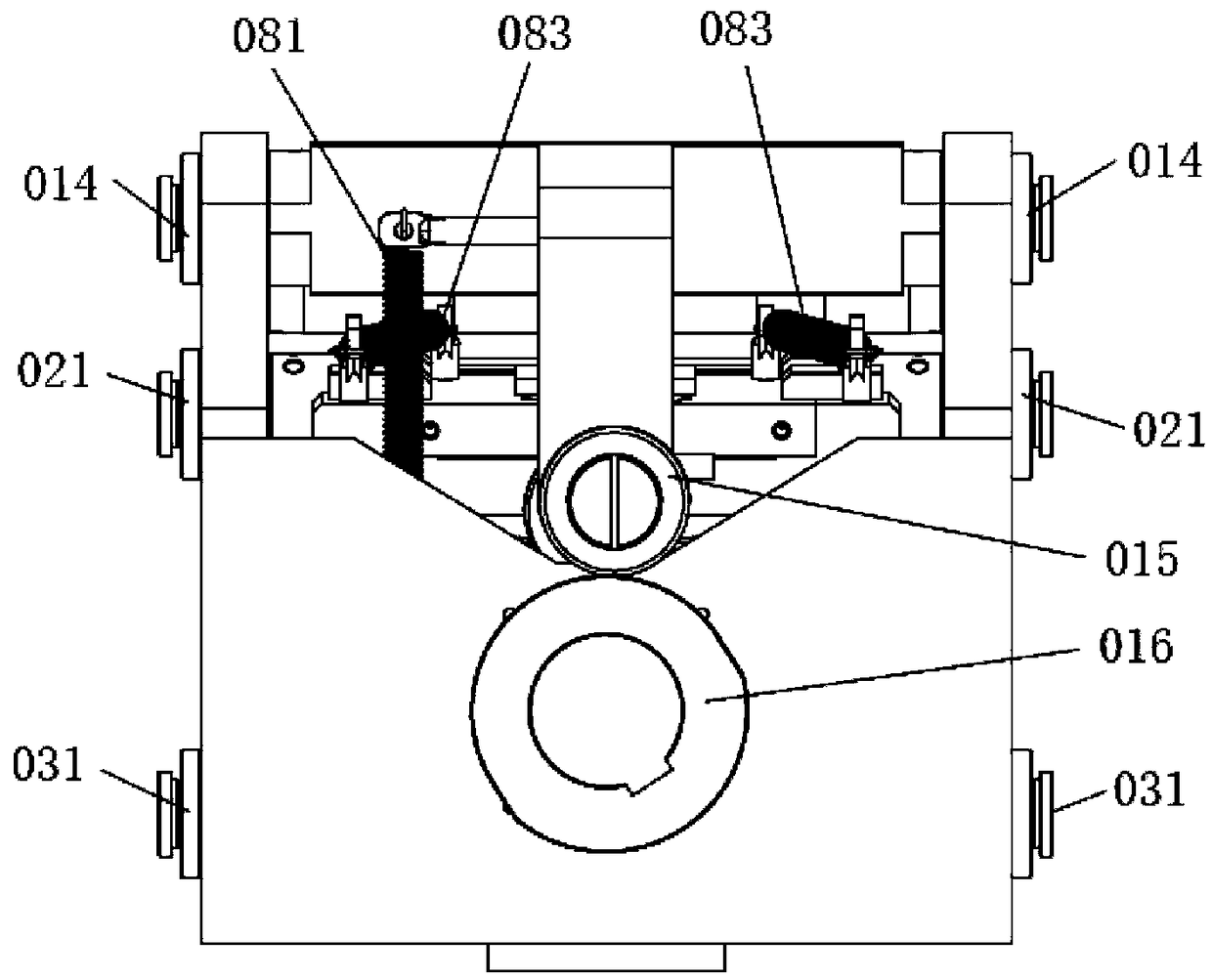
[0048] Such as Figure 1-3 As shown, this embodiment discloses a metal sheet flanging device, which can flang the metal sheet to its lower surface, such as figure 1 shown. The metal sheet flanging device includes a housing 090, a clamping mechanism for clamping the metal sheet, and a flanging mechanism capable of flanging the metal sheet. The flanging mechanism includes a pressing block 050 for flanging the metal sheet, and the pressing block 050 needs to tilt and move to the downward pressing plate 011, and pushes the part of the metal sheet to be flanged to be bent to complete the flanging.

[0049] Specifically, the clamping mechanism includes an upper pressing plate 012, a lower pressing plate 011 and a first lever mechanism, the lower pressing plate 011 is fixed on the casing 090, the upper pressing plate 012 is fixed on one end of the movable plate A013 of the first lever mechanism, and the fulcrum of the first lever mechanism A014 is arranged on the shell 090, and the...

Embodiment 2

[0061] Such as Figure 11-14 As shown, the metal sheet flanging equipment of the second embodiment is basically the same as the first embodiment above, and this embodiment only describes the differences between the two, and the same structure will not be repeated here.

[0062] In this embodiment, the metal sheet flanging equipment can flang the metal sheet to its upper surface. Correspondingly, the pressure block 050 in the flanging mechanism needs to be tilted and moved to the upper pressing plate 012 .

[0063] For this reason, the upper platen 012 in the clamping mechanism is provided with a slope for flanging the metal sheet; see Figure 13 The movable plate B022 in the flanging mechanism is provided with a roller B023 near one end of the briquetting block 050, the roller B023 contacts the cam B024, and when the flange B0241 of the cam B024 contacts the roller B023, the briquetting block 050 moves up. Afterwards, under the action of the flanging mechanism and the moving ...


PUM


Abstract

The invention relates to metal sheet forming machining equipment and discloses metal sheet flanging equipment. The metal sheet flanging equipment comprises a shell, a clamping mechanism and a flangingmechanism. The clamping mechanism comprises an upper pressing plate, a lower pressing plate and a first lever mechanism. The lower pressing plate is fixed to the shell, and the upper pressing plate is fixed to one end of a movable plate A of the first lever mechanism. The pivot point A of the first lever mechanism is arranged on the shell, and the first lever mechanism drives the upper pressing plate to be close to the lower pressing plate. The upper pressing plate or the lower pressing plate is provided with an inclined face for metal sheet flanging. The flanging mechanism comprises a secondlever mechanism, a swing mechanism and a movable plate. A pressing block is arranged at the end, close to the upper pressing plate, of the movable plate. The pivot point B of the second lever mechanism is arranged on the shell, and a movable plate B of the second lever mechanism is in sliding connection with the movable plate and used for driving the pressing block to vertically move. A swing plate of the swing mechanism pushes the end, provided with the pressing block, of the movable plate to be close to the upper pressing plate or the lower pressing plate. According to the metal sheet flanging equipment, the problems that when a metal punching process is adopted, the production cost is high, and the production efficiency is low are solved.

Description

technical field [0001] The invention relates to the technical field of metal sheet forming and processing equipment, in particular to a metal sheet flanging equipment. Background technique [0002] Metal sheet is widely used in the field of containers and packaging boxes due to its characteristics of easy forming, recyclability and durability. [0003] When the metal box is processed and closed, it usually needs to be flanged (or ticked) on its opposite two sides, so that the two ends of the metal sheet are closed. At present, the metal stamping process is still used for the forming of some thinner and easier to form low-strength metal sheets, which will obviously lead to higher production costs and lower production efficiency. [0004] For this reason, there is an urgent need to provide a metal sheet flanging device to solve the above problems. Contents of the invention [0005] The object of the present invention is to provide a sheet metal flanging equipment to realiz...

Claims


Application Information

Patent Timeline
IPC IPC(8): B21D19/00B21D43/00
CPCB21D19/00B21D43/003
Inventor 盛小园杜明威
Owner 东莞市中腾自动化设备制造有限公司
Why Eureka
Try Eureka