Automatic feeding mechanism for minisized round bars and installation method of automatic feeding mechanism for minisized round bars

An automatic feeding and bar material technology, which is applied to machine tools, grinders, metal processing, etc. designed for grinding the rotating surface of workpieces, can solve the problems of serious bar material jamming, low efficiency, and unstable feeding, and achieve less jamming , high efficiency, stable feeding effect

Pending Publication Date: 2018-12-07
六安市新突破机械设备有限公司
View PDF10 Cites 2 Cited by
  • Summary
  • Abstract
  • Description
  • Claims
  • Application Information

AI Technical Summary

Problems solved by technology

[0003] The main purpose of the present invention is to provide an automatic feeding mechanism and installation method for miniature round b

Method used


Image

  • Automatic feeding mechanism for minisized round bars and installation method of automatic feeding mechanism for minisized round bars
  • Automatic feeding mechanism for minisized round bars and installation method of automatic feeding mechanism for minisized round bars
  • Automatic feeding mechanism for minisized round bars and installation method of automatic feeding mechanism for minisized round bars

Examples


Embodiment 1

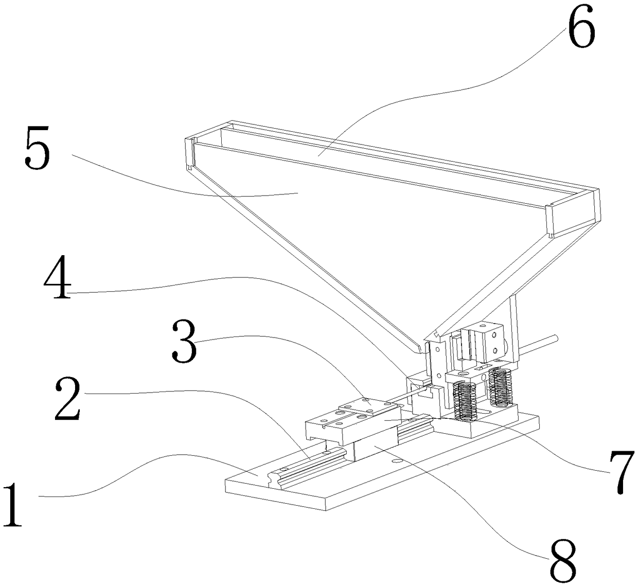
[0022] Such as Figure 1-3 As shown, a micro-bar automatic feeding mechanism includes a base 1, a linear guide rail 2, an ejector rod pressing plate 3, an ejector rod 4, a hopper front baffle 5, a hopper unloading mechanism 6, an ejector rod fixing block 7, Slider 8, the base 1 is fixed with a linear guide rail 2 by screws, the linear guide rail 2 is slidably matched with the slider 8, the slider 8 is fixedly installed with a fixing block 7 for the ejector rod, and the fixing block 7 for the ejector rod is provided with an ejector Rod 4 and ejector rod 4 are provided with an ejector rod pressure plate 3, which is fixed on the ejector rod fixing block 7 by screws, one end of the base 1 is fixedly installed with a hopper unloading mechanism 6, and one end of the hopper unloading mechanism A hopper front baffle 5 is inserted.

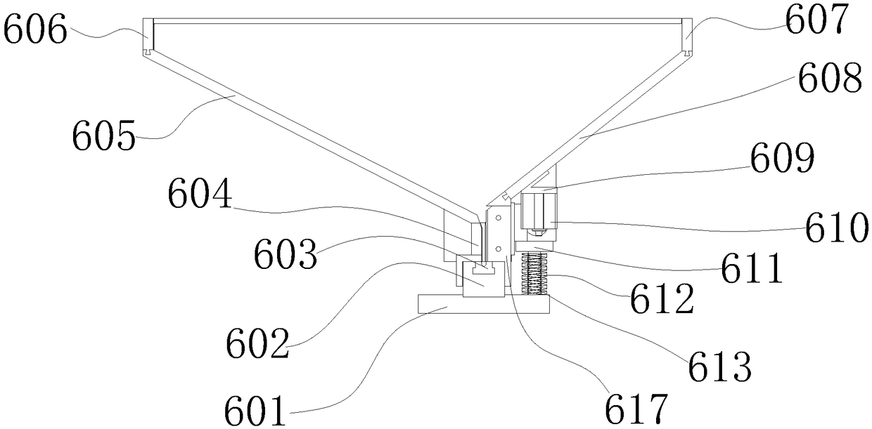
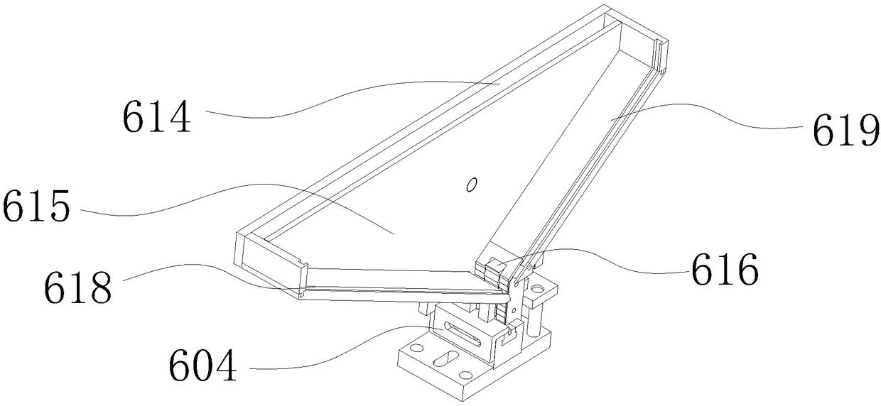
[0023] In this embodiment, the hopper feeding mechanism 6 includes a hopper base plate 601, an insert fixing seat 602, an insert 603, a hopper side plate...

Embodiment 2

[0032] An installation method of a micro-bar automatic feeding mechanism, including the following process, step 1, the assembly of the base, fixing the linear guide rail on the base through screws, installing the slider on the linear guide rail, and fixing the ejector rod on the On the fixed block of the ejector rod, cover the ejector rod pressing plate on the fixed block of the order rod, fix the ejector rod, and fix the fixed block of the ejector rod on the slider through screws; step 2, the hopper support Assemble, fix the insert fixing seat on the side of the bottom plate of the hopper, install the insert on the insert fixing seat, and put the V-shaped groove of the insert facing the ejector rod, so that the ejector rod and the V-shaped groove of the insert are in the same position On the straight line, fix and install the hopper base plate and the base with screws, and combine one side of the hopper base plate with one end of the linear guide rail; Step 3, assemble the hop...


PUM


Abstract

The invention discloses an automatic feeding mechanism for minisized round bars. The automatic feeding mechanism for the minisized round bars comprises a base, a linear guide rail, an ejector rod pressing plate, an ejector rod, a hopper front baffle, a hopper discharging mechanism, an ejector rod fixing block and a sliding block, wherein the linear guide rail is fixedly installed on the base through screws and is in sliding fit with the sliding block; the ejector rod fixing block is fixedly installed on the sliding block and provided with the ejector rod; the ejector rod pressing plate is arranged on the ejector rod and fixedly installed on the ejector rod fixing block through screws; the hopper discharging mechanism is fixedly installed at one end of the base; and the hopper front baffleis inserted at one end of the hopper discharging mechanism. The invention further discloses an installation method of the automatic feeding mechanism for the minisized round bars. The installation method comprises the steps of base assembly, hopper support assembly, hopper base assembly, hopper assembly, power component assembly, testing and trial operation. According to the automatic feeding mechanism for the minisized round bars and the installation method of the automatic feeding mechanism for the minisized round bars, feeding is stable, the probability of blocking is low, efficiency is high, operation and adjustment are convenient, and the labor and time are saved.

Description

technical field [0001] The invention relates to the technical fields of automatic lathe processing and centerless grinding processing, in particular to an automatic feeding mechanism and installation method for miniature round bar materials. Background technique [0002] When automatic lathes, centerless mills, etc. process micro-bars, the existing automatic feeder is usually used to feed the materials by vibrating inventory. The bars are seriously jammed and the feeding is not stable, which affects the production efficiency and causes low production efficiency. Contents of the invention [0003] The main purpose of the present invention is to provide an automatic feeding mechanism and installation method for miniature round rods, which are used to solve the problems of serious rod jamming, unstable feeding and low efficiency in existing automatic feeding machines [0004] In order to achieve the above object, the technical solution adopted by the present invention is: a m...

Claims


Application Information

Patent Timeline
IPC IPC(8): B23B15/00B24B5/35
CPCB23Q7/00B23Q7/10B24B5/355
Inventor 姜磊沈先伟
Owner 六安市新突破机械设备有限公司
Why Eureka
Try Eureka