Plate cutting machine

A cutting machine and plate technology, applied in the field of plate processing, can solve the problems of time-consuming and laborious replacement of cutters, low cutting efficiency, time-consuming and labor-intensive, etc., and achieve the advantages of reducing lumbar muscle strain, simple structure, and reducing tool changing time. Effect

Pending Publication Date: 2018-12-07
芜湖龙鳞汽车部件有限公司
View PDF1 Cites 6 Cited by
  • Summary
  • Abstract
  • Description
  • Claims
  • Application Information

AI Technical Summary

Problems solved by technology

[0002] Plate refers to a flat rectangular building material plate of standard size, including forged, rolled or cast metal plate, steel plate or iron plate, etc. Metal plate is very commonly used in industrial production. In the field of plate processing and production, technological It is necessary to cut the board. The existing production line generally uses a board cutting machine. In the prior art, the saw blade of the board cutting machine is usually circular. During the working process, the circular saw blade is driven by a motor to rotate continuously. , the feeding mechanism continuously drives the plate forward, so that the plate passes through the rotating saw blade to complete the cutting of the plate, but different products require different cutting angles and precision, so it is necessary to replace or increase the cutter frequently, which is time-consuming and laborious, and different The degree of bending of tall employees is different when working, which may cause health problems such as lumbar muscle strain in the long run. Therefore, the market urgently needs a cutting machine with strong practicability
[0003] Chinese patent application CN108080721A discloses a plate cutting machine, including a base and a cutter; one end of...

Method used


Image

  • Plate cutting machine
  • Plate cutting machine
  • Plate cutting machine

Examples


Embodiment 1

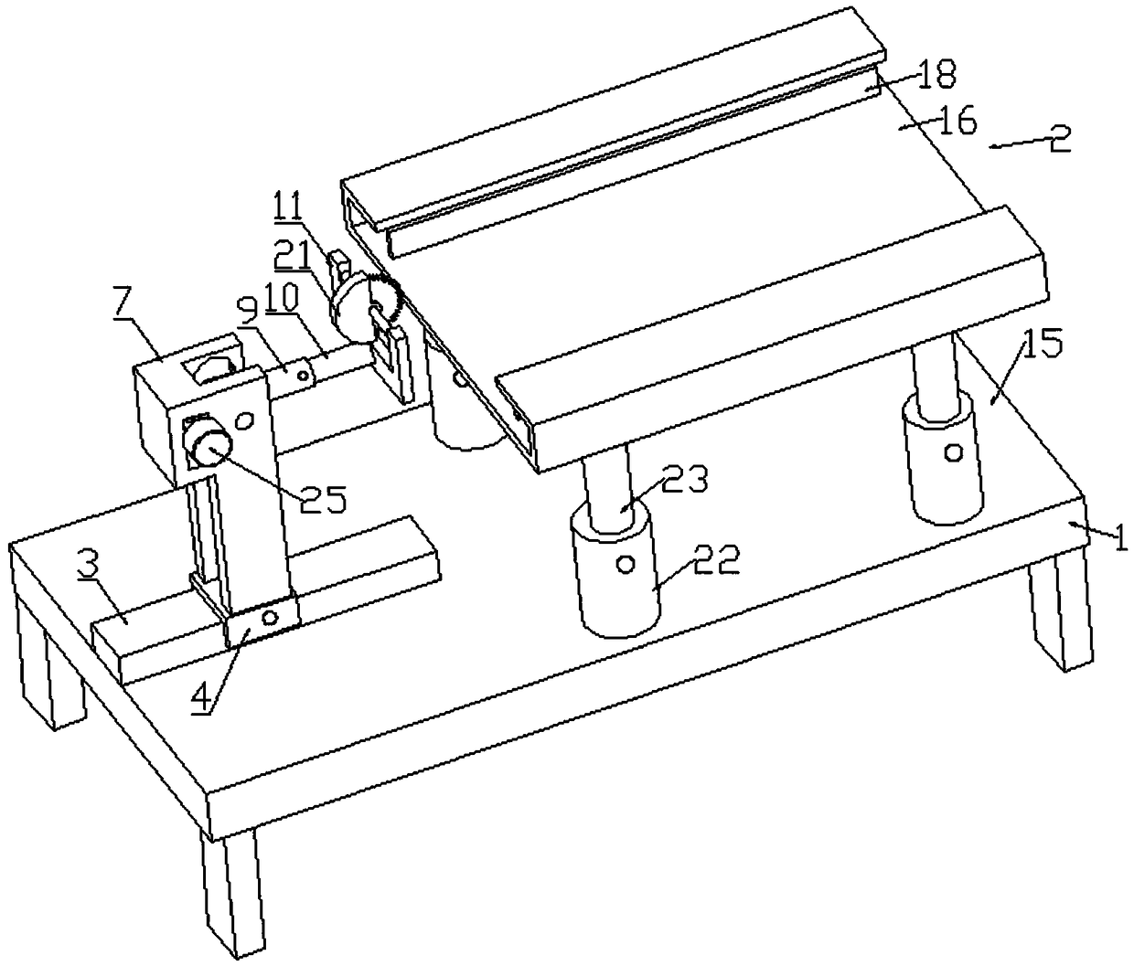
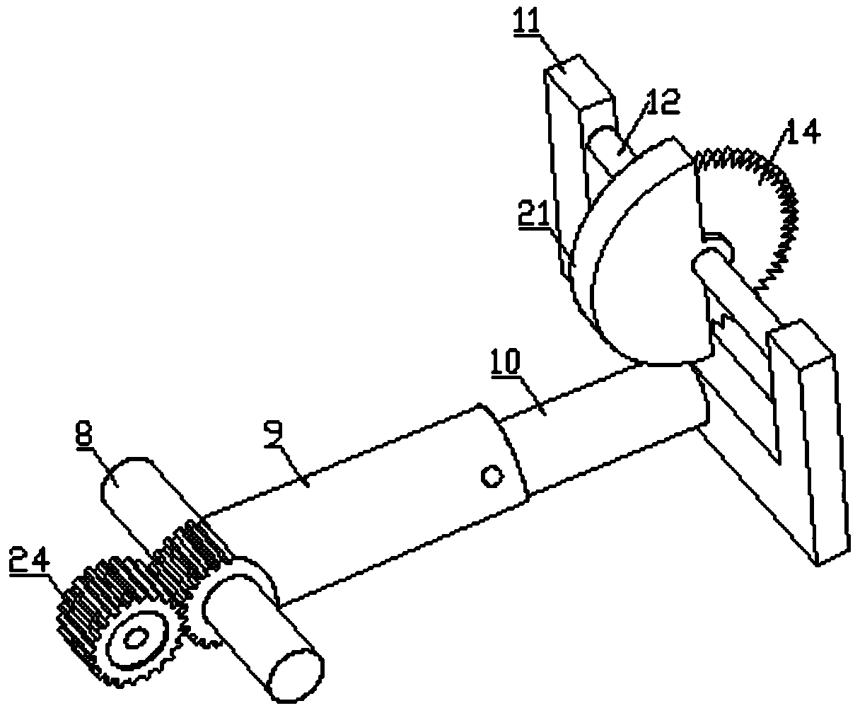
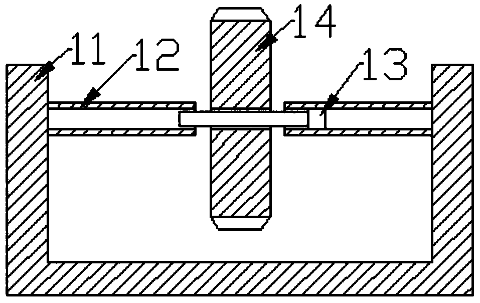
[0021] Such as Figure 1 to Figure 6 As shown, a plate cutting machine includes a worktable 1, on which a support 2 and a guide rail 3 are fixedly installed, the guide rail 3 is slidably connected to a sliding plate 4, and the sliding plate 4 is provided with screw holes and The guide rail 3 is connected by tightening screws. The guide rail 3 is provided with a driving mechanism 5, the sliding plate 4 is provided with a rack 6, and the driving mechanism 5 drives the rack 6 and the sliding plate 4 to move linearly along the guide rail 3. The sliding plate 4 is fixedly connected to a bracket 7, and the two brackets 7 are rotated to connect a cross bar 8. The middle part of the cross bar 8 is sleeved with a special-shaped sleeve 9, and the end of the special-shaped sleeve 9 is sleeved with a sleeve rod 10 and connected by fastening screws , The sleeve rod 10 is fixedly connected to the cutter holder 11, and the cutter holder 11 is fixed with a connecting shaft 12, the shaft 12 is ...

Embodiment 2

[0024] Such as Figure 1 to Figure 6 As shown, a plate cutting machine includes a worktable 1, on which a support 2 and a guide rail 3 are fixedly installed, the guide rail 3 is slidably connected to a sliding plate 4, and the sliding plate 4 is provided with screw holes and The guide rail 3 is connected by tightening screws. The guide rail 3 is provided with a driving mechanism 5, the sliding plate 4 is provided with a rack 6, and the driving mechanism 5 drives the rack 6 and the sliding plate 4 to move linearly along the guide rail 3. The sliding plate 4 is fixedly connected to a bracket 7, and the two brackets 7 are rotated to connect a cross bar 8. The middle part of the cross bar 8 is sleeved with a special-shaped sleeve 9, and the end of the special-shaped sleeve 9 is sleeved with a sleeve rod 10 and connected by fastening screws , The sleeve rod 10 is fixedly connected to the cutter holder 11, and the cutter holder 11 is fixed with a connecting shaft 12, the shaft 12 is ...


PUM


Abstract

The invention discloses a plate cutting machine and relates to the technical field of plate machining. The plate cutting machine comprises a working table; a mounting supporting seat and a guiding rail are fixed to the working table; a sliding plate is in sliding connection to the guiding rail; and a driving mechanism is disposed in the guiding rail. The plate cutting machine is simple in structure, and convenient to operate; by arranging a second upright column, height in a first upright column can be adjusted, height adjustment of the supporting seat can be achieved so as to adapt to operators with the different heights, lumbar muscle degeneration and the like caused by long-time bending of people with the different heights are reduced, and the practicability is high; and the position ofthe sliding plate on the guiding rail is moved, the position of a sleeve rod in an abnormal-shaped sleeve is adjusted, and a small gear drives the abnormal-shaped sleeve to rotate, thus transverse displacement and angle change of a cutter are achieved, the working efficiency is improved, multi-angle cutting can be achieved, and the cutter changing time is shortened.

Description

Technical field [0001] The invention relates to the technical field of sheet metal processing, in particular to a sheet metal cutting machine. Background technique [0002] Plate refers to a standard size flat rectangular building material plate, including forged, rolled or cast metal plates, steel plates or iron plates, etc. Metal plates are very commonly used in industrial production. In the field of plate processing and production, the process is It is necessary to cut the plate. The existing production line generally uses a plate cutting machine. In the prior art, the saw blade of the plate cutting machine is usually circular. During the working process, the circular saw blade is driven by a motor to continuously rotate , The feeding mechanism continuously drives the plate forward, so that the plate can be cut through the rotating saw blade. However, different products require different cutting angles and precision, so it is necessary to frequently replace or increase the cut...

Claims


Application Information

Patent Timeline
IPC IPC(8): B23D45/00B23D47/02
CPCB23D45/00B23D47/02
Inventor 胡万胜朱统坤宇宙凌静
Owner 芜湖龙鳞汽车部件有限公司
Why Eureka
Try Eureka