
Vacuum laser sealing welding tool and vacuum laser sealing machine

A laser and vacuum technology, applied in laser welding equipment, auxiliary devices, manufacturing tools, etc., can solve the problems of high deviation, limited product application, and high cost

Pending Publication Date: 2018-12-07
东晶电子金华有限公司
View PDF6 Cites 9 Cited by
  • Summary
  • Abstract
  • Description
  • Claims
  • Application Information

AI Technical Summary

Problems solved by technology

However, due to the large size tolerance of the fixture position hole, the cover plate is more offset relative to the base after laser sealing and welding, and the outer dimension of the product has a larger deviation, the application of this fixing method is limited.
The other is to use pressure claws or spring columns to press the cover plates one by one, and use a set of laser sealing welding system to perform diagonal spot welding or pre-weld half of the cover plate in a nitrogen environment, and then send it into the vacuum chamber for further processing. The whole periphery of the cover plate and the base is laser welded. This fixing method requires two sets of laser sealing and welding systems for sealing and welding. The equipment is complicated and the cost is high.

Method used


Image

  • Vacuum laser sealing welding tool and vacuum laser sealing machine
  • Vacuum laser sealing welding tool and vacuum laser sealing machine
  • Vacuum laser sealing welding tool and vacuum laser sealing machine

Examples


Embodiment Construction

[0034] In order to understand the above-mentioned purpose, features and advantages of the present invention more clearly, the present invention will be further described in detail below in conjunction with the accompanying drawings and specific embodiments. It should be noted that, in the case of no conflict, the embodiments of the present application and the features in the embodiments can be combined with each other.

[0035] In the following description, many specific details are set forth in order to fully understand the present invention. However, the present invention can also be implemented in other ways different from those described here. Therefore, the protection scope of the present invention is not limited by the specific details disclosed below. EXAMPLE LIMITATIONS.

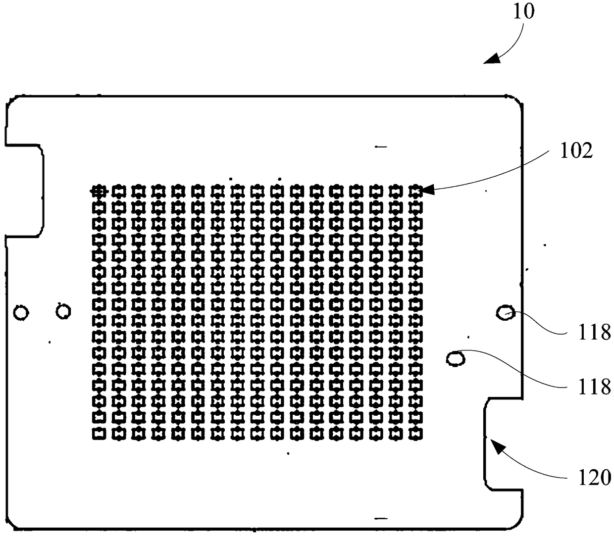
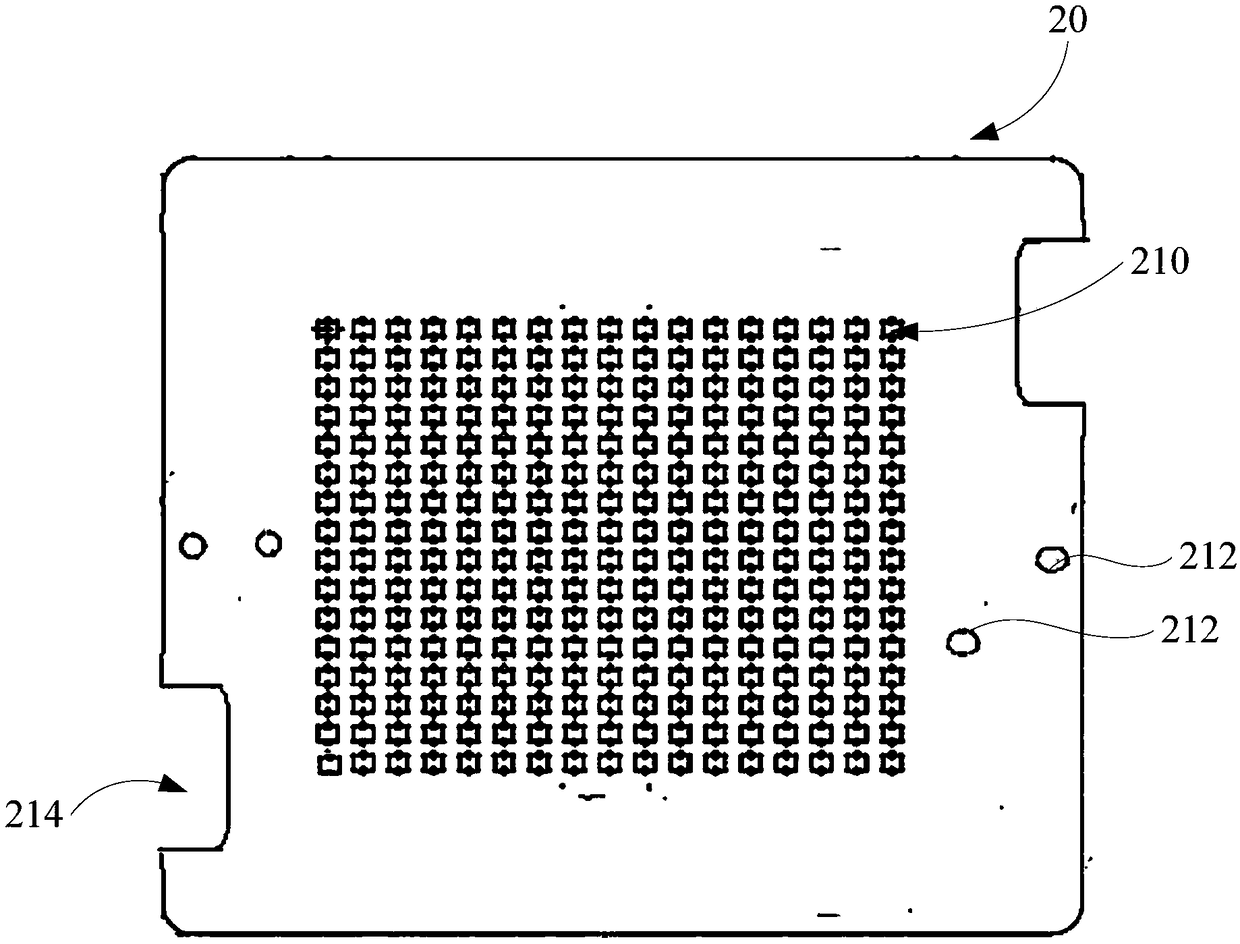
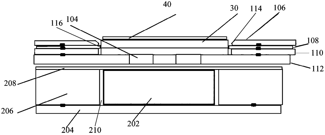
[0036] Refer below Figure 1 to Figure 3 The vacuum laser sealing and welding tool and vacuum laser sealing and welding machine according to some embodiments of the present invention are described. ...


PUM

PropertyMeasurementUnit
thicknessaaaaaaaaaa

Abstract

The invention provides a vacuum laser sealing welding tool and a vacuum laser sealing machine. The vacuum laser sealing tool comprises a sealing welding plate and a magnetic attraction plate, a plurality of workpiece mounting grooves are formed in the sealing welding plate, openings of the workpiece mounting groove faces upwards, and workpiece bases are installed in the workpiece mounting grooves;a plurality of magnetic attraction pieces are arranged on the magnetic attraction plate, the magnetic attraction plate is detachably arranged below the sealing welding plate, and the center positionsof the magnetic attraction pieces correspond to the center positions of the workpiece mounting grooves in a one-to-one correspondence mode; and when workpiece cover plates are installed above the workpiece bases, the magnetic attraction pieces can attract the workpiece cover plates so that the workpiece cover plates can be fixed on the workpiece bases. According to the vacuum laser sealing welding tool, the center positions of the magnetic attraction pieces arranged in the magnetic attraction plate correspond to the center positions of the workpiece mounting grooves in a one-to-one mode, so that when the workpiece cover plates are installed above the workpiece bases, the magnetic attraction force generated by the magnetic attraction pieces enables the workpiece cover plates to be tightlyfixed to the workpiece bases, and then the workpiece bases and the workpiece cover plates can be directly conveyed into a vacuum chamber for vacuum laser sealing welding.

Description

technical field [0001] The invention relates to the technical field of sealing and welding equipment, in particular to a vacuum laser sealing and welding tool and a vacuum laser sealing and welding machine. Background technique [0002] Quartz crystal resonators are one of the key components of various communication electronic digital products. In recent years, with the development of intelligent communication and various digital technologies, there are more and more smart electronic products for people's livelihood consumption, which also drives its supporting There is a huge demand for the key components of quartz crystal resonators. The traditional packaging methods of quartz crystal resonators are parallel resistance welding or low-temperature glass welding. In recent years, laser welding has begun to introduce crystal resonators due to its low cost and high efficiency. Cover and base package manufacturing field. However, the vacuum laser sealing and welding of the base...

Claims


Application Information

Patent Timeline
Patent Type & Authority Applications(China)
IPC IPC(8): B23K26/20B23K26/12B23K26/70B23K37/04
CPCB23K26/1224B23K26/206B23K26/70B23K37/0443
Inventor 辜批林潘春琴李庆跃骆红莉林土全黄文俊郭雄伟柯晨帆王幡慧
Owner 东晶电子金华有限公司
Learn More