Multi-steel pipe welding device based on truss

A welding device and steel pipe technology, applied in welding equipment, auxiliary devices, auxiliary welding equipment, etc., can solve the problems of affecting the quality of use and low efficiency, and achieve the effect of being beneficial to welding and easy to operate.

Active Publication Date: 2019-12-10
CHENGDU ZHIRONG ZHICHUANG INTPROP MANAGEMENT CO LTD
View PDF7 Cites 0 Cited by
  • Summary
  • Abstract
  • Description
  • Claims
  • Application Information

AI Technical Summary

Problems solved by technology

[0004] The technical problem to be solved by the present invention is that the existing truss has low efficiency during welding and will affect the quality of later use. The purpose is to provide a multi-steel pipe welding device based on truss and solve the problem of truss steel pipe welding

Method used


Image

  • Multi-steel pipe welding device based on truss
  • Multi-steel pipe welding device based on truss

Examples


Embodiment 1

[0028] like figure 1As shown, the multi-steel pipe welding device based on truss of the present invention includes steel pipes for welding into trusses and a fixing device for fixing steel pipes. The fixing device includes a first fixing plate 1 and a second fixing plate 2, and the first fixing plate 1 Located directly above the second fixed plate 2, the first fixed plate 1 is provided with a first through groove 8 in its length direction, and the first through groove 8 divides the first fixed plate 1 into two small fixed plates. A first telescopic plate 9 and a second telescopic plate 10 that expand and contract along the width direction of the first fixed plate 1 on the horizontal plane are respectively arranged on the opposite faces of the two small fixed plates, and the first telescopic plate 9 and the second telescopic plate 10 are opposite to each other. One end is vertically connected with a fixed plate 11 for fixing the steel pipe, the steel pipe is fixedly connected b...

Embodiment 2

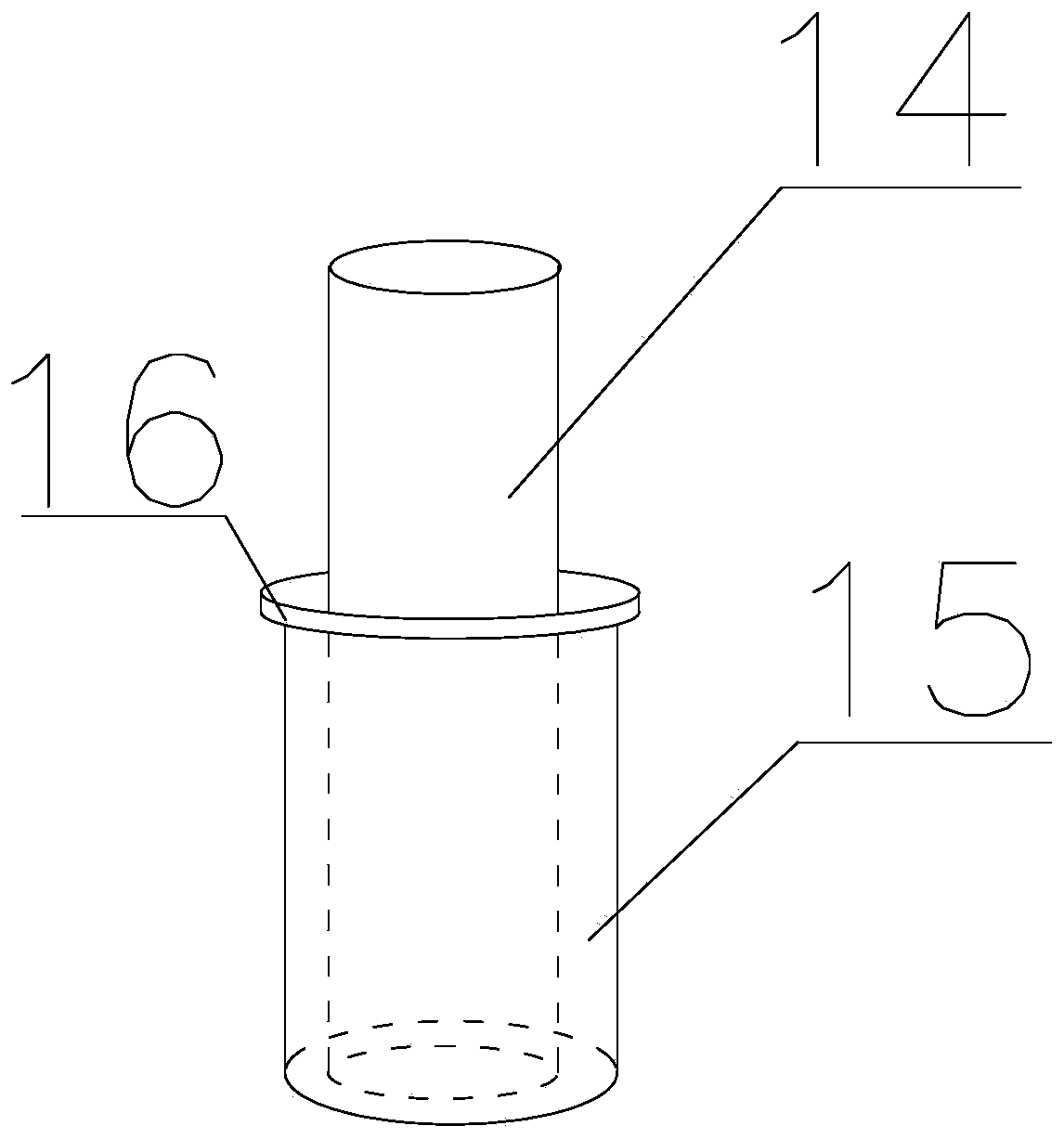
[0030] Based on the truss-based multi-steel welding device, on the basis of Embodiment 1, the connecting rod 14 is fixedly set with a stabilizing plate 16, and the connecting rod 14 and the stabilizing plate 16 are provided with corresponding convex grooves and grooves, and the stabilizing plate 16 is used to connect The axis of the bar 14 is the axis rotation, and the upper end of the stabilizing plate 16 is fixedly connected with the rotating bar 15, and when the rotating bar 15 is rotated, the stabilizing plate 16 is driven to rotate; The bottom is provided with a corresponding draw-in groove, and the lower ends of the rotating rod 15 and the connecting rod 14 are fixedly connected to the inner bottom of the second fixed plate 2, and the rotating rod 15 and the connecting rod 14 are on the inner bottom of the second fixed plate 2 along its The axis rotates; the distance between the upper end of the rotating rod 15 and the upper end of the second fixed plate 2 is 8cm. The he...

Embodiment 3

[0032] Based on the multi-steel pipe welding device based on the truss, on the basis of Embodiment 2, when the opposite surfaces of the two fixed plates 11 are in contact with each other, the first expansion plate 9 and the second expansion plate 10 are both in a compressed state. Protruding lines and corresponding fixing grooves are respectively provided on the opposite surfaces of the two fixing plates 11 , and when the two fixing plates 11 are in contact, the raised lines are sequentially snapped into the fixing grooves. The rectangle surrounded by the four second through-slots 12 and the rectangle surrounded by the four third through-slots 13 are squares with the same size.


PUM


Abstract

The invention discloses a multi-steel pipe welding device based on a truss. The lower ends of a connecting rod and a rotating rod are contacted and connected with the inner bottom of a second fixed plate; the connecting rod and the rotating rod are rotated on the second fixed plate; an external thread A is arranged on the side surface of the rotating rod; an internal thread A corresponding to theexternal thread A is arranged in a third through groove on a connecting plate; the upper end of the rotating rod is between a first fixed plate and the second fixed plate; the distance between the connecting plate and the inner bottom of the second fixed plate is adjusted through rotation of the rotating rod; multiple external threads B are arranged on the side surface, above the rotating rod, ofthe connecting rod; internal threads B corresponding to the external threads B are arranged in a second through groove; and the distance between the first fixed plate and the second fixed plate is adjusted through rotation of the connecting rod. The device is simple in structure and convenient to operate and use.

Description

technical field [0001] The invention relates to the construction field, in particular to a multi-steel pipe welding device based on a truss. Background technique [0002] Truss: A structure consisting of members connected to each other by hinges at both ends. The truss is composed of straight rods and generally has a plane or space structure of triangular units. The truss members mainly bear axial tension or pressure, so that the strength of the material can be fully utilized. When the span is large, it can save materials compared with solid web beams, reduce self-weight and Increase stiffness. [0003] However, when the existing trusses are welded, two people are required to fix and connect the two rods respectively, and then weld them. This operation is not only inefficient, but also the quality of the obtained trusses is poor, and it cannot be welded well. , which in turn will affect the quality of the truss, which is not conducive to the later use of the truss. Conte...

Claims


Application Information

Patent Timeline
Patent Type & Authority Patents(China)
IPC IPC(8): B23K37/04B23K37/053
CPCB23K37/0443B23K37/0533
Inventor 黄欢
Owner CHENGDU ZHIRONG ZHICHUANG INTPROP MANAGEMENT CO LTD
Why Eureka
Try Eureka