A line-to-line drainage structure of a low-lying structure section of a maglev rail transit

A maglev track and line-to-line technology, which is applied in the direction of tracks, roads, ballast layers, etc., can solve the problems of subgrade structure disturbance, long construction period, and increased excavation depth of cutting sections, and achieve easy project investment and simple construction procedures , The effect of short construction period

Pending Publication Date: 2018-12-07
CHINA RAILWAY MAGLEV TRANSPORTATION INVESTMENT CONSTR CO LTD
View PDF0 Cites 1 Cited by
  • Summary
  • Abstract
  • Description
  • Claims
  • Application Information

AI Technical Summary

Problems solved by technology

[0004] However, the use of the line-to-line drainage ditch scheme has the following disadvantages: 1. The line-to-line ditch and the water collection well need to be implemented after the subgrade construction is completed. During the implementation, it is necessary to cut or excavate the foundation pit in the subgrade structure, which will cause a large disturbance to the subgrade structure. The galvanized steel pipe needs to be pre-embedded, which will interfere with the subgrade filling construction to a certain extent; 2. The ditch between the lines and the water collection well are all reinforced concrete structures, and the project investment is relatively large, and on-site reinforcement binding, vertical formwork, pouring concrete and maintenance are required. The construction process is relatively complicated and the construction period is long; 3. The water collection well and the galvanized steel pipe are generally not less than 1.5m below the subgrade surface, and it is not suitable for maintenance during operation; 4. To ensure that the drainage in the galvanized pipe is discharged into the side ditch, The elevation of the bottom of the side ditch needs to be deepened, resulting in an increase in the excavation depth of the cutting section, which increases the earthwork and investment

Method used


Image

  • A line-to-line drainage structure of a low-lying structure section of a maglev rail transit
  • A line-to-line drainage structure of a low-lying structure section of a maglev rail transit
  • A line-to-line drainage structure of a low-lying structure section of a maglev rail transit

Examples


Embodiment Construction

[0027] In order to make the object, technical solution and advantages of the present invention clearer, the present invention will be further described in detail below in conjunction with the accompanying drawings and embodiments. It should be understood that the specific embodiments described here are only used to explain the present invention, not to limit the present invention. In addition, the technical features involved in the various embodiments of the present invention described below can be combined with each other as long as they do not constitute a conflict with each other.

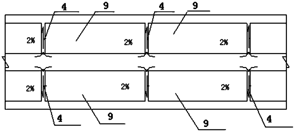
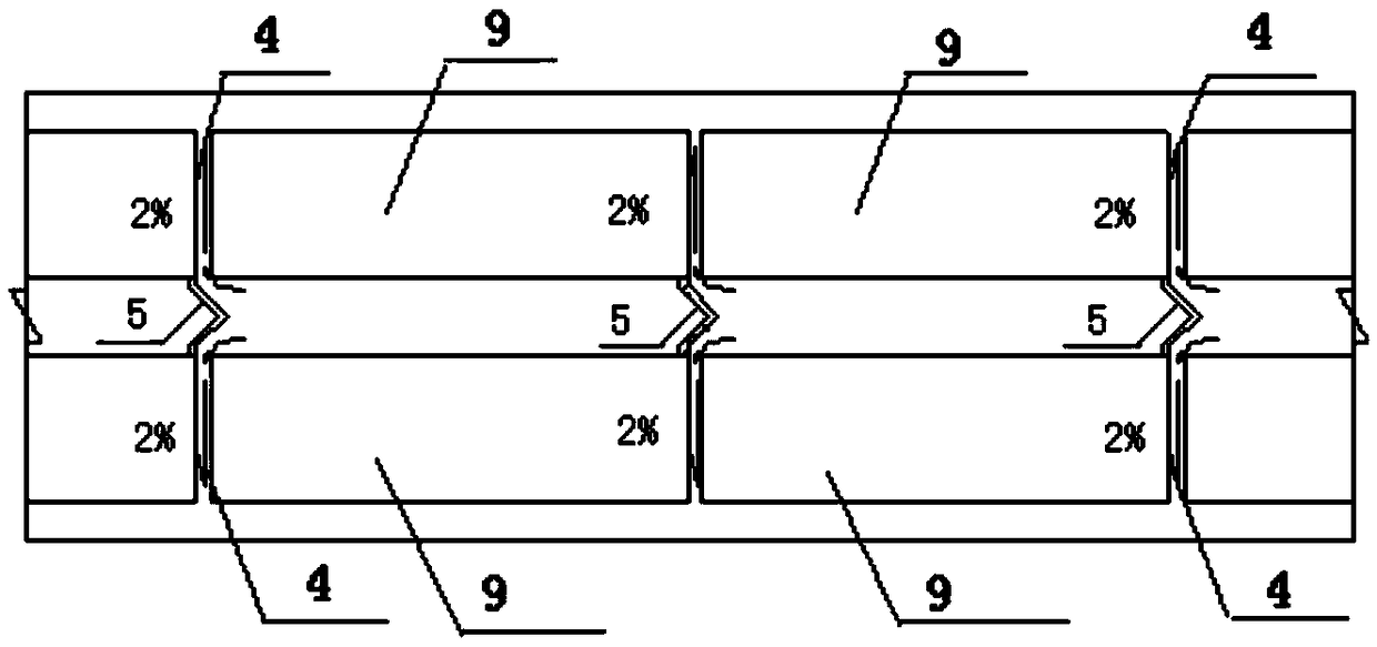
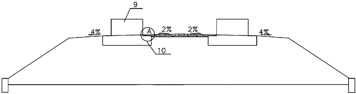
[0028] figure 1 It is a structural schematic diagram of a cross-section of a line-to-line drainage structure in a low-lying structure section of a maglev rail transit according to an embodiment of the present invention. figure 2 for figure 1 Enlarged image at A. Such as figure 1 and figure 2 As shown, in the low-set structure section of the two-line maglev rail transit, the track beams 9 ...


PUM


Abstract

A line-to-line drainage structure of a low-lying section of a maglev rail transit comprises a drainage layer 3 and a transverse drainage channel 4, the drainage layer (3) is arranged between the railbeam bases (10), and the drainage layer (3) extends to both sides to cover the top surface of the rail beam base (10), the top surface of the drainage layer (3) is a drainage transverse slope (6) witha height higher than the height of both sides of the track at the centerline of the roadbed surface, forming a pavement inclined to both sides between the lines, wherein the transverse drainage channels (4) are arranged at the expansion joints (7) of the rail beams, the height of one side close to the lines is higher than the height of the outside of the tracks, and the transverse drainage channels (4) are used for draining the water collected between the lines from the center of the roadbed surface to both sides through the drainage transverse slopes (6), and then draining the water collected between the lines to the shoulders of the two sides. The inter-line drainage structure of the maglev rail transit low-lying structure section realizes inter-line drainage on the basis of avoiding large-scale excavation, and has short construction period and easy maintenance.

Description

technical field [0001] The invention belongs to the technical field of maglev rail transit, and more particularly relates to a drainage structure between lines of low-lying structure sections of maglev rail transit. Background technique [0002] When the low-level structure section of the maglev rail transit is double-line, since the two-line track beams are arranged along the length of the line, the height of the structure is higher than the subgrade surface, and the catchment water between the lines cannot be discharged to both sides of the line. [0003] In the prior art, the maglev express line is provided with inter-line ditch for drainage. The specific scheme of drainage is as follows: a 0.4×0.6m drainage ditch is set between the lines at the center of the subgrade surface, and the inter-line catchment water is introduced into the inter-line drainage ditch. Set up a water collection well every 50m, the section size of the water collection well is 0.6×0.7m, and then use...

Claims


Application Information

Patent Timeline
Patent Type & Authority Applications(China)
IPC IPC(8): E01B25/30E01B1/00
CPCE01B25/30E01B1/008E01B25/305
Inventor 丁兆锋韦随庆周飞苏谦孙斌金陵生王大为
Owner CHINA RAILWAY MAGLEV TRANSPORTATION INVESTMENT CONSTR CO LTD
Why Eureka
Try Eureka