
Clamp for template reinforcing

A formwork reinforcement and fixture technology, which is applied in the connection of formwork/formwork/work frame, the preparation of building components on site, construction, etc., can solve the problem of fastening and dismantling, cleaning and recycling of materials, labor-intensive man-hours, and turnover of materials Unfavorable unified storage management, increased project labor costs and other issues, to achieve the effect of unified recycling management, cost control, and cost control

Pending Publication Date: 2018-12-07
ZHEJIANG CONSTR INVESTMENT GRP CO LTD
View PDF0 Cites 2 Cited by
  • Summary
  • Abstract
  • Description
  • Claims
  • Application Information

AI Technical Summary

Problems solved by technology

[0002] The traditional formwork reinforcement uses a combination of sporadic components such as mountain cards, irons, and nuts. The operator uses a wrench to tighten the nuts step by step. The reinforcement time is relatively long and the construction progress is relatively slow. The thread thread, the bite force of the thread pattern is relatively inferior to the sawtooth, so the traditional formwork reinforcement often has quality problems such as mold explosion due to nut slippage and thread cracking; due to the complicated process of traditional formwork reinforcement and demolition engineering, the tightening of the nut Fixing and dismantling and cleaning and recycling of materials consume a lot of labor hours, which greatly increases the labor cost of the project; materials are miscellaneous, large in quantity, and small in size, and turnover materials such as mountain cards, irons, and nuts are not conducive to unified access In the process of construction, there is no loss and loss, and the overall recycling rate is low

Method used


Image

  • Clamp for template reinforcing
  • Clamp for template reinforcing
  • Clamp for template reinforcing

Examples


Embodiment Construction

[0026] The present invention will be further described below in conjunction with the accompanying drawings of the description.

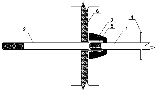
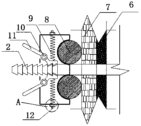
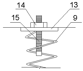
[0027] Such as Figure 1-4 As shown, a fixture for formwork reinforcement, including fixed screw 1, detachable wall bolt 2, rubber bowl 3, water stop piece 4, internal thread sleeve 5, formwork 6, square wood 7, steel pipe 8, pressure Tighten spring 9, fixed shaft 10, trigger 11, clamp housing 12, spring seat 13, adjusting nut 14, thread adjusting rod 15, trigger lever 16, trigger head 17 and connecting sleeve 18.

[0028] The detachable wall-through bolt 2 is connected with both ends of the fixed screw 1, and the two ends of the fixed screw 1 are provided with external threads, and the middle position is fixed with a water-stop sheet 4. One end of the detachable wall-through bolt 2 is provided with an internal thread sleeve 5, and the other end There is a first inverted tooth structure, and the detachable wall-through bolt 2 is fixedly connected wi...


PUM


Abstract

The invention discloses a clamp for template reinforcing and relates to the technical field of building template fixing. The clamp comprises a fixing screw, detachable through-wall bolts connected with the two ends of the fixing screw, and a clamp device arranged on the detachable through-wall bolts. The clamp device comprises a clamp shell, a fixing shaft arranged on the clamp shell, and a trigger arranged on the fixing shaft in a matched mode. A pressing spring is arranged on the clamp shell, one end of the pressing spring is connected with the clamp shell, and the other end of the pressingspring is fixedly connected with the trigger. A clamping groove is formed in one side of the clamp shell, and bolt mounting holes are formed in the middle of the clamp shell. The detachable through-wall bolts are arranged in the bolt mounting holes in a penetrating mode to be matched with the trigger, and a backing stopping self-locking structure is constituted. The clamp has the beneficial effects that operation is convenient, the construction schedule is accelerated advantageously, connecting is tight, and the engineering quality is guaranteed advantageously.

Description

technical field [0001] The invention relates to the technical field of building formwork installation, in particular to a clamp for formwork reinforcement. Background technique [0002] The traditional formwork reinforcement uses a combination of sporadic components such as mountain cards, irons, and nuts. The operator uses a wrench to tighten the nuts step by step. The reinforcement time is relatively long and the construction progress is relatively slow. The thread thread, the bite force of the thread pattern is relatively inferior to the sawtooth, so the traditional formwork reinforcement often has quality problems such as mold explosion due to nut slippage and thread cracking; due to the complicated process of traditional formwork reinforcement and demolition engineering, the tightening of the nut Fixing and dismantling and cleaning and recycling of materials consume a lot of labor hours, which greatly increases the labor cost of the project; materials are miscellaneous,...

Claims


Application Information

Patent Timeline
Patent Type & Authority Applications(China)
IPC IPC(8): E04G17/065
CPCE04G17/065E04G17/0658Y02E10/20
Inventor 丁世龙冯星火朱汐赵柏钧陈成
Owner ZHEJIANG CONSTR INVESTMENT GRP CO LTD
Learn More