Collector air inlet device of centrifugal fan

A centrifugal fan and current collector technology, which is applied to the components of the pumping device for elastic fluids, machines/engines, mechanical equipment, etc., to achieve the effects of convenient use, simple structure, and easy processing and forming.

Pending Publication Date: 2018-12-07
LOW SPEED AERODYNAMIC INST OF CHINESE AERODYNAMIC RES & DEV CENT
View PDF0 Cites 6 Cited by
  • Summary
  • Abstract
  • Description
  • Claims
  • Application Information

AI Technical Summary

Problems solved by technology

However, the large-scale turbulent air vortex in the air inlet area is one of the main reasons for the aerodynamic noise of the centrifugal fan

Method used


Image

  • Collector air inlet device of centrifugal fan
  • Collector air inlet device of centrifugal fan
  • Collector air inlet device of centrifugal fan

Examples


Embodiment 1

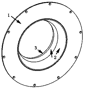
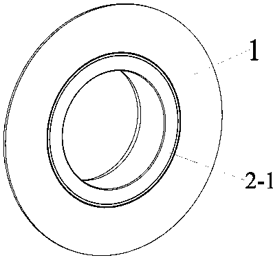
[0035] like image 3 As shown, the diversion unit is designed as a triangular arc structure, such as Figure 4 The cross-section of the entire circle of air guide unit shown in the figure is completely connected tangentially to the arc surface, and is integrated by screws or riveting. The air flow passing surface of the arc surface and the triangular arc unit is a plane, and the arc is 0°, close to the air inlet The area is flush with the end face of the collector.

Embodiment 2

[0037] like Figure 5 As shown, the guide unit is designed as a sawtooth structure, with several sawtooth surfaces evenly distributed in the same circumferential direction. The sawtooth surface is perpendicular to the axis of the air inlet of the centrifugal fan and flush with the end face of the collector. The two are connected by screws or rivets. The sawtooth angle and sawtooth height can be adjusted according to the noise characteristics of the centrifugal fan; in this example, the sawtooth height is 10mm, and the sawtooth angle is 30 o , the distance between sawtooth and sawtooth is 20mm, the number of sawtooth is 22, and the thickness of sawtooth is 5mm.

Embodiment 3

[0039] like Image 6 As shown, the guide unit is designed as a concave groove structure, and several grooves are evenly distributed in the same circumferential direction. The angle formed by the length direction of the groove unit and the axial direction of the air inlet of the centrifugal fan is 10°. The two are connected by screws or Rivet connection. The groove depth, groove width, and angle between the groove direction and the axial direction of the fan inlet can be adjusted according to the noise characteristics of the centrifugal fan; The pitch of the trough is 20mm, and the number of trough units is 22.


PUM


Abstract

The invention discloses a collector air inlet device of a centrifugal fan. A collector comprises an arc surface. A flow guide unit is arranged on the arc surface. The flow guide unit is fixedly connected with the arc surface as a whole. The highest point of the arc surface is tangent to the flow guide unit. The optimized air inlet collector does not generate great effect on the aerodynamic performance of the fan. The structure is relatively simple, and machining and shaping are easy. The replaceable flow guide unit component of the air inlet collector can be selected based on noise characteristics of the centrifugal fan, and structure parameters are optimized. The flow guide unit, as a replaceable component, has the characteristic of being convenient to use.

Description

technical field [0001] The invention belongs to the field of centrifugal fans, and in particular relates to a collector air inlet device of a centrifugal fan, which can be applied to ventilation systems of factories, cooling towers, vehicles, households, etc., wind tunnel wind sources, and inflation and propulsion of hovercraft And aerospace cabin fans, etc. Background technique [0002] The centrifugal fan collector is usually installed in the air inlet area, which can accelerate the airflow in this area and form a uniform velocity field and pressure field at the fan inlet to reduce flow loss and improve fan efficiency. As an important auxiliary part of the centrifugal fan, the structure of the collector not only affects its aerodynamic performance, but also affects the noise characteristics. At present, there are four commonly used forms, namely cylindrical, conical, arc-shaped and nozzle-shaped, and the cross-sections are all circular. The airflow surface of these four ...

Claims


Application Information

Patent Timeline
Patent Type & Authority Applications(China)
IPC IPC(8): F04D29/44F04D29/66
CPCF04D29/441F04D29/663F04D29/667
Inventor 左孔成陈正武李征初宋玉宝马瑞轩赵昱冉学军黄奔
Owner LOW SPEED AERODYNAMIC INST OF CHINESE AERODYNAMIC RES & DEV CENT
Why Eureka
Try Eureka