Magnetic attraction type locking and positioning device

A locking positioning and magnetic suction technology, which is applied in the direction of fixing devices, mechanical equipment, etc., can solve the problems of restricting the development and application of locking positioning devices, the service life of parts is too short, and the precision requirements of parts are high, so as to achieve compact structure and easy replacement. The effect of convenient parts and mechanism taking up a lot of space

Pending Publication Date: 2018-12-07
南京奥特自动化有限公司
View PDF9 Cites 8 Cited by
  • Summary
  • Abstract
  • Description
  • Claims
  • Application Information

AI Technical Summary

Problems solved by technology

[0002] For some movable equipment parts, it is often necessary to lock and locate reliably at a specific location to meet specific functions or working conditions. For this reason, locking and positioning devices have emerged and are widely used in various mechanical equipment. Traditional In machinery, the self-locking properties of mechanical structures, such as threads, eccentric wheels, and connecting rod mechanisms, are often used to achieve the purpose of locking equipment, and these mechanisms are either cumbersome to operate and limited in use; or the structure is relatively complex and the accuracy of the parts is relatively high high; or the service life of the parts is too short, the replacement is inconvenient, etc., which limit the development and application of the locking and positioning device; therefore, developing a locking and positioning device that can overcome the above defects has become a technology to be urgently solved by those skilled in the art question

Method used


Image

  • Magnetic attraction type locking and positioning device
  • Magnetic attraction type locking and positioning device

Examples


Embodiment 1

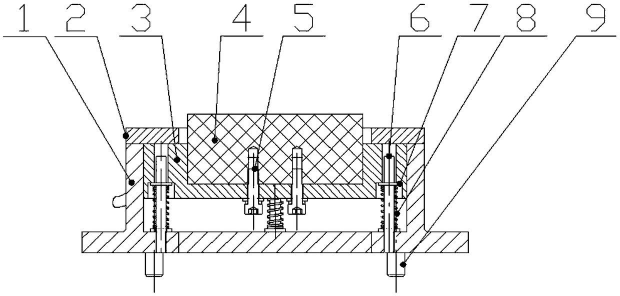
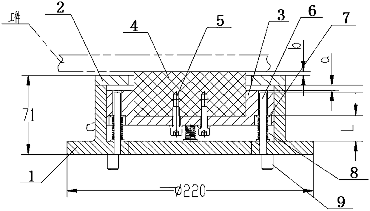
[0033] A magnetic locking and positioning device provided in this embodiment has a structure such as Figure 1-2 As shown, it includes a base 1, a cover plate 2, an electromagnetic chuck 4, an electromagnetic chuck support seat 3, a spring guide rod 6 and a supporting compression spring 8, and the electromagnetic chuck 4 is arranged on the electromagnetic chuck support seat 3, carrying the electromagnetic chuck 4 The electromagnetic chuck support seat 3 is arranged in the base 1, the spring guide rod 6 provided with a supporting compression spring 8 is arranged between the electromagnetic chuck support seat 3 and the base 1, and the cover plate 2 is arranged on the base, wherein:

[0034] The electromagnetic chuck support seat 3 is provided with a groove compatible with the electromagnetic chuck 4, the electromagnetic chuck support seat 3 is provided with assembly holes, the bottom end of the electromagnetic chuck support seat 3 is provided with a fixing hole, and the screw 5 p...


PUM


Abstract

The invention discloses a magnetic attraction type locking and positioning device. The magnetic attraction type locking and positioning device comprises a base, a cover plate, an electromagnetic suction cup, an electromagnetic suction cup supporting base, spring guiding rods and supporting type compression springs. The electromagnetic suction cup is arranged on the electromagnetic suction cup supporting base, and the electromagnetic suction cup supporting base bearing the electromagnetic suction cup is arranged in the base. The spring guiding rods sleeved with the supporting type compression springs are arranged between the electromagnetic suction cup supporting base and the base, and the cover plate is arranged on the base. The device can adjust the pre-tightening force, low-voltage direct current power supply is utilized, and the beneficial effects of stability, strong attraction force and small residual magnetism after the power failure are achieved; and functions are safer and morereliable, the structure is simple and economical, and mounting, dismounting, maintaining and component replacement are convenient.

Description

technical field [0001] The invention relates to a positioning device used for locking, positioning and fixing of magnetic induction materials, and belongs to the technical field of equipment manufacturing. Background technique [0002] For some movable equipment parts, it is often necessary to lock and locate reliably at a specific location to meet specific functions or working conditions. For this reason, locking and positioning devices have emerged and are widely used in various mechanical equipment. Traditional In machinery, the self-locking properties of mechanical structures, such as threads, eccentric wheels, and connecting rod mechanisms, are often used to achieve the purpose of locking equipment, and these mechanisms are either cumbersome to operate and limited in use; or the structure is relatively complex and the accuracy of the parts is relatively high high; or the service life of the parts is too short, the replacement is inconvenient, etc., which limit the devel...

Claims


Application Information

Patent Timeline
Patent Type & Authority Applications(China)
IPC IPC(8): F16B1/00
CPCF16B1/00F16B2200/83
Inventor 朱小明
Owner 南京奥特自动化有限公司
Why Eureka
Try Eureka