Oil collecting device for air compressor safety valve

A technology of oil collecting device and safety valve, which is applied in the direction of engine lubrication, mechanical equipment, engine components, etc., and can solve problems such as operation stability, consumption cost, and machine oil pollution

Pending Publication Date: 2018-12-07
釜玛机械(江苏)有限公司
View PDF0 Cites 0 Cited by
  • Summary
  • Abstract
  • Description
  • Claims
  • Application Information

AI Technical Summary

Problems solved by technology

[0002] In the prior art, if the pressure difference between the inside and outside of the hollow compressor oil and gas barrel is too large when the machine is turned on, the safety valve will release the pressure through the pressure relief nozzle, causing the oil in the oil and gas barrel to be ejected from the pressure relief nozzle of the safety valve, causing oil pollution to the machine pollution, and even if an oil collection device is added to the pressure relief nozzle, the oil collection device needs to be replaced and maintained regularly after long-term use, the operation remains unchanged, and the cost is consumed

Method used


Image

  • Oil collecting device for air compressor safety valve
  • Oil collecting device for air compressor safety valve
  • Oil collecting device for air compressor safety valve

Examples


Embodiment Construction

[0024] The present invention will now be described in further detail with reference to the accompanying drawings. These drawings are all simplified schematic diagrams, and only illustrate the basic structure of the present invention in a schematic manner, so they only show the structures related to the present invention.

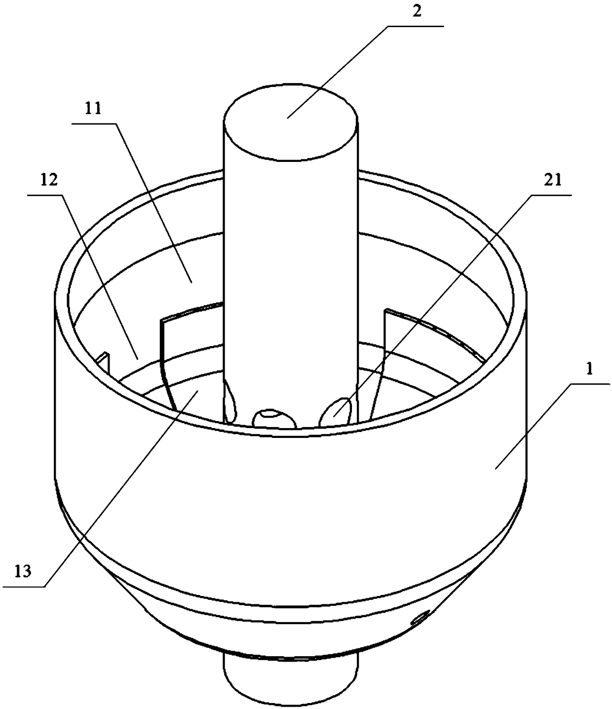
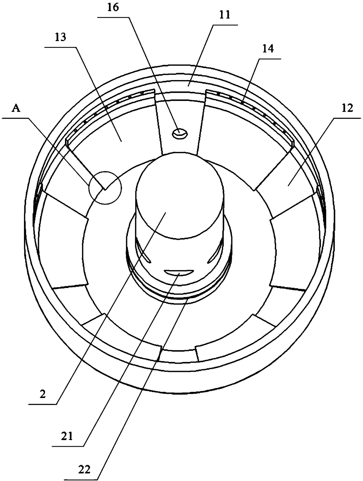
[0025] like Figure 1-5 As shown in the figure, it is used for the oil collecting device on the safety valve of the air compressor. The oil collecting device is installed on one side of the air compressor head 3. The oil collecting device includes an integrated oil collecting cover 1 and a safety valve body 2 to avoid For the oil leakage that may be caused by the long-term use of the connecting part of the two, the outer wall of the oil collecting cover 1 is formed into a cone, and the inner wall is formed into a parabola, which is in line with the movement trend of the fluid gathering together after sliding down, which is more conducive to the falling and c...


PUM


Abstract

The invention relates to an oil collecting device for an air compressor safety valve. The oil collecting device is installed on one side of an air compressor head (3) for keeping the interior of an air compressor clean, and the oil utilization rate is increased. The oil collecting device is additionally installed on the safety valve, oil is sprayed to the inner wall of the oil collecting device, slides along the curved shape of the inner wall downwards and is collected in a centralized mode, the oil collecting device is connected to an intake valve through an oil return pipe, and recycling ofoil is achieved.

Description

technical field [0001] The invention relates to the technical field of air compressors, in particular to an oil collecting device used on a safety valve of an air compressor. Background technique [0002] In the prior art, if the pressure difference between the inside and outside of the oil and gas barrel of an air compressor is too large when the machine is turned on, the safety valve will release the pressure through the pressure relief nozzle, causing the oil in the oil and gas barrel to be ejected from the pressure relief nozzle of the safety valve, causing oil pollution to the machine. Even if an oil collection device is added to the pressure relief nozzle, it is necessary to regularly replace and maintain the oil collection device after long-term use, the operation remains unchanged, and the cost is consumed. SUMMARY OF THE INVENTION [0003] The technical problem to be solved by the present invention is: In order to overcome the deficiencies and defects existing in ...

Claims


Application Information

Patent Timeline
Patent Type & Authority Applications(China)
IPC IPC(8): F16N31/02F16N39/06
CPCF16N31/02F16N39/06
Inventor 金权中许孟龙吴彦钧王丽霞
Owner 釜玛机械(江苏)有限公司
Why Eureka
Try Eureka