
Slag machine

A technology of slag removal machine and slag bin, applied in the field of slag removal machine, which can solve the problems of high cost of medicines, easy slag accumulation and blockage of slag removal machine

Active Publication Date: 2019-10-15
CHINA SHENHUA ENERGY CO LTD +2
View PDF5 Cites 0 Cited by
  • Summary
  • Abstract
  • Description
  • Claims
  • Application Information

AI Technical Summary

Problems solved by technology

[0004] The purpose of the present invention is to provide a slag removal machine to solve the problems that the slag removal machine is easy to accumulate slag and blockage, and the cost of medicine is high

Method used


Image

  • Slag machine

Examples


Embodiment Construction

[0032] Specific embodiments of the present invention will be described in detail below in conjunction with the accompanying drawings. It should be understood that the specific embodiments described here are only used to illustrate and explain the present invention, and are not intended to limit the present invention.

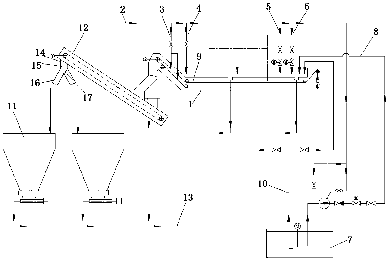
[0033] The present invention provides a slag removal machine, wherein the slag removal machine includes:

[0034] A scraper pool 1, in which a scraper and a chain 9 that drives the scraper to move;

[0035] The main water supply pipeline 2, the main water supply pipeline 2 is provided with the chain flushing water pipeline 3 connected to the slag removal tank 1, the manual door continuous water supply pipeline 4, the electric door water supply pipeline 5 and the electric door emergency water supply pipeline 6 ;

[0036] Pool 7;

[0037] The emergency water supply pipeline 8 of the slag scraper, the inlet of the emergency water supply pipeline 8 of the slag sc...


PUM


Abstract

The invention relates to the field of slag dredging machines, and discloses a slag dredging machine. The slag dredging machine comprises a slag dredging pool (1), a main water supply pipeline (2) provided with a chain flushing water pipeline (3), a manual door continuous water supply pipeline (4), an electric door water supply pipeline (5) and an electric door emergency water supply pipeline (6),a water collecting pool (7), and a slag dredging machine emergency water supply pipeline (8); and along with lowering of the liquid level of the slag dredging pool (1), the electric door water supplypipeline (5), the electric door emergency water supply pipeline (6) and the slag dredging machine emergency water supply pipeline (8) are opened in sequence. In the slag dredging machine, a concentrator, a concentrator sewage pump, a dedusting water pump and a slag water medicine charging system are canceled; the slag dredging pool is basically not disturbed by the external, so that the precipitation effect is better; and the water collecting pool only receives less water without easily generating blockage, so that the slag dredging machine is reliably operated, and the slag dredging efficiency is improved.

Description

technical field [0001] The invention relates to the field of slag removing machines, in particular to a slag removing machine. Background technique [0002] In the existing wet slag removal method of thermal power plants, the slag discharged from the boiler slag well is pulled out by the scraper slag extractor, and then enters the slag bin through the scraper conveyor for transportation. The overflow water of the slag extractor is discharged into the sump, and is pumped to the high-efficiency thickener of the slag water system through the bottom slag drainage pump. The ash sedimentation is accelerated on the inclined plate of the high-efficiency thickener, and the concentrated ash is returned by the sewage pump of the high-efficiency thickener to the ascending section of the slag extractor, and then taken out by the slag extractor to the slag bin for transportation. The high-efficiency concentrator clarifies the water, enters the clear water tank, adds scale inhibitors and ...

Claims


Application Information

Patent Timeline
Patent Type & Authority Patents(China)
IPC IPC(8): F23J1/06
Inventor 任健
Owner CHINA SHENHUA ENERGY CO LTD
Learn More