
Negative pressure air jet deep well dewatering device of foundation pit

A deep well precipitation and air jet technology, which is applied in infrastructure engineering, construction, etc., can solve the problems of reduced precipitation efficiency, slow precipitation speed, waste of human resources, etc., and achieve the effects of easy construction, increased precipitation speed, and high work efficiency

Active Publication Date: 2015-01-07
冯克俊
View PDF10 Cites 14 Cited by
  • Summary
  • Abstract
  • Description
  • Claims
  • Application Information

AI Technical Summary

Problems solved by technology

In order to prevent changes in the underground surroundings from causing harm to the environment and facilities around the foundation pit, the method of lowering the groundwater level at deep well points is generally used to solve such technical problems. The three problems that need to be solved for the dewatering of deep well points are: It is to increase the depth of precipitation, the second is to reduce the moisture content of the foundation soil, and the third is to increase the drainage speed in the early stage of precipitation. Vacuum foundation pit deep well dewatering equipment" and ZL200520047130.7 "Foundation pit deep well point dewatering equipment" discloses deep well well point dewatering equipment. Although this technical solution has achieved certain results in actual construction, there are still some defects. One is that in the early stage of precipitation, that is, when the groundwater level is high, the precipitation rate is slow, resulting in a decrease in precipitation efficiency; the other is that the depth of the vacuum distribution pipe in the well pipe needs to be adjusted continuously according to the groundwater level, resulting in a waste of human resources

Method used


Image

  • Negative pressure air jet deep well dewatering device of foundation pit
  • Negative pressure air jet deep well dewatering device of foundation pit
  • Negative pressure air jet deep well dewatering device of foundation pit

Examples


Embodiment Construction

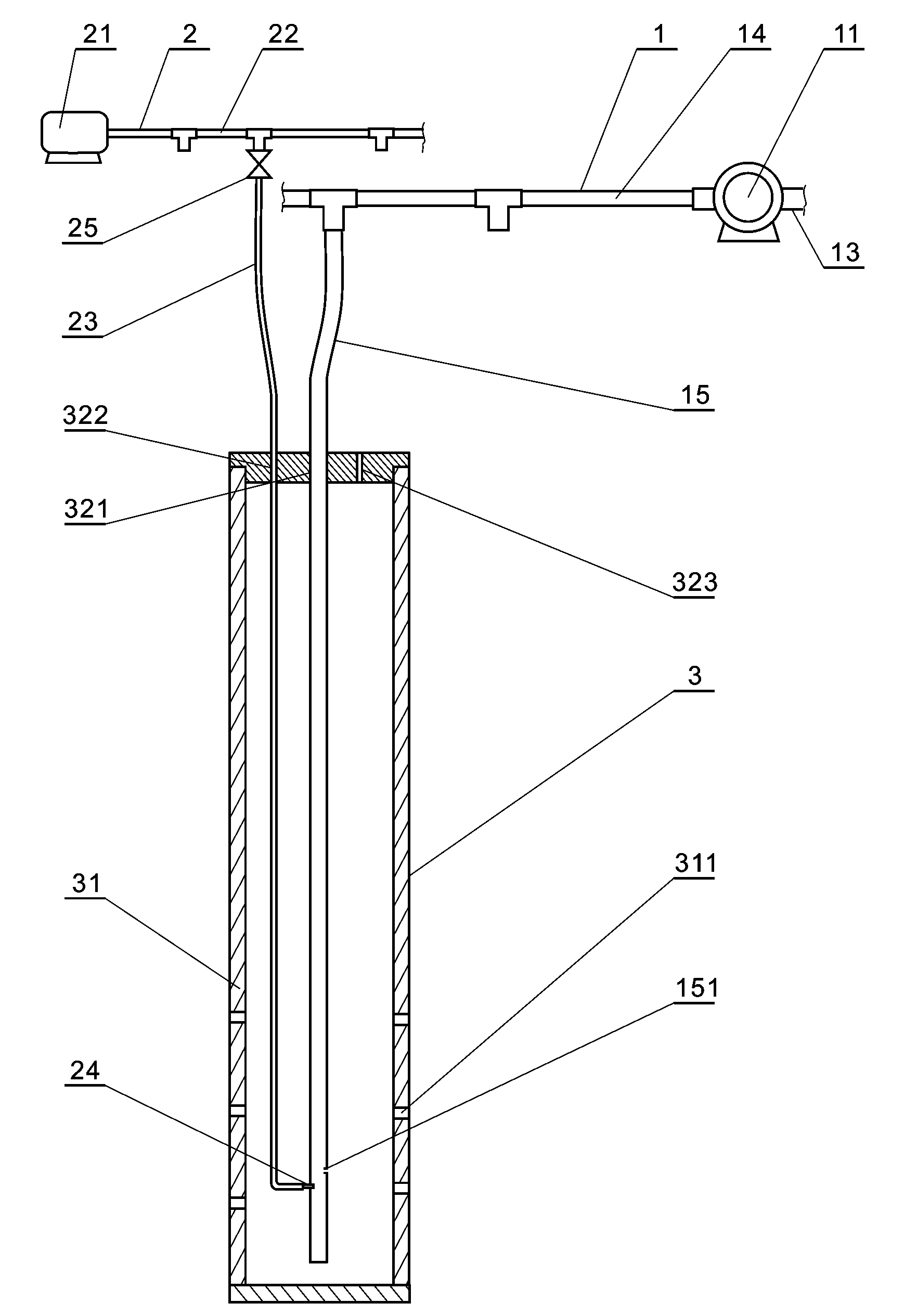
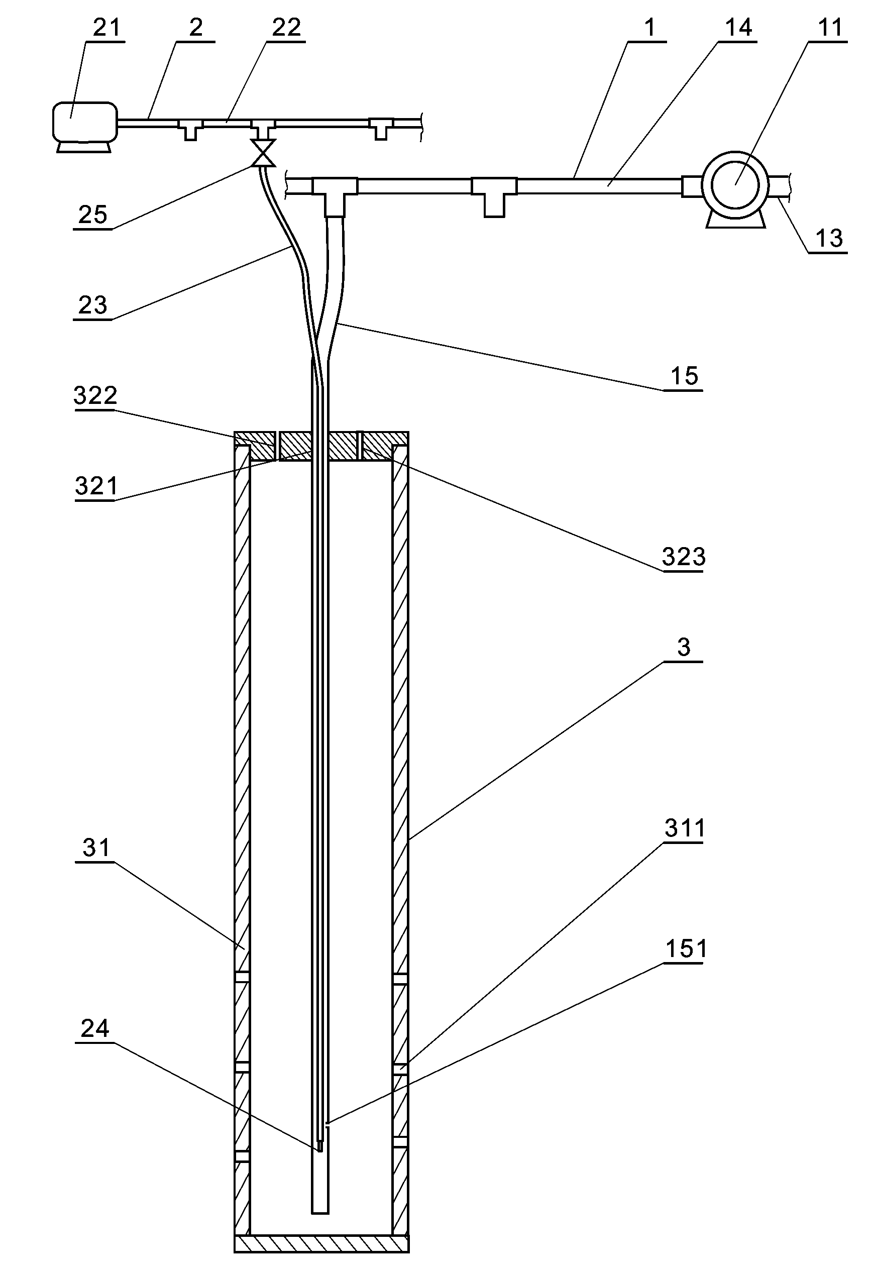
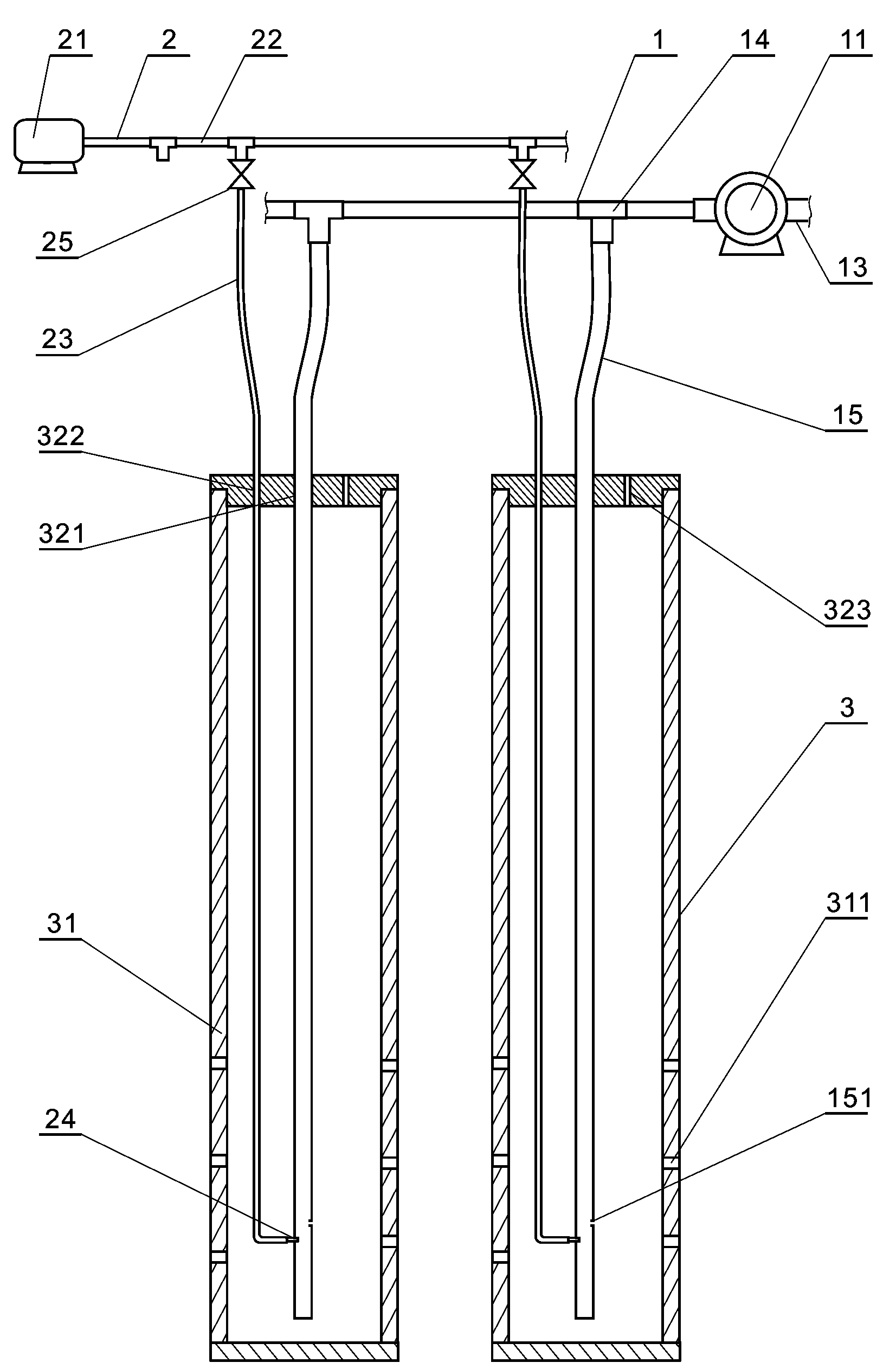
[0012] refer to figure 1 , figure 2 , the present invention includes negative pressure system 1, positive pressure system 2 and deep well pipe assembly 3, described negative pressure system 1 is made up of vacuum pump 11, drainage pipe 13, vacuum main water pipe 14 and vacuum water distribution pipe 15, positive pressure system 2 is made up of empty Compressor 21, air main pipe 22, air branch pipe 23, on-off valve 25 and gas nozzle 24 are composed. Deep well pipe assembly 3 is composed of well pipe 31 and well cover 32. There are vacuum tube holes 321, air tube holes 322 and ventilation holes 323, the bottom of the well tube 31 is closed, and small holes 311 are provided in the tube body;

[0013] The drainage pipe 13 and the vacuum water main pipe 14 of the negative pressure system 1 are respectively connected to the two ends of the vacuum pump 11, the vacuum water distribution pipe 15 is connected to the vacuum water main pipe 14 and extends into the well pipe 31 through t...


PUM


Abstract

The invention discloses a negative pressure air jet deep well dewatering device of a foundation pit. The negative pressure air jet deep well dewatering device comprises a negative pressure system, a positive pressure system and a deep well pipe assembly. The negative pressure system is composed of a vacuum pump, a drain pipe, a vacuum water main and a vacuum branch water pipe. The positive pressure system is composed of an air compressor, an air main, a branch air pipe, a switching valve and an air tap. The deep well pipe assembly is composed of a well pipe and a well cover. The vacuum branch water pipe of the negative pressure system extends into the well pipe through the well cover. The branch air pipe of the positive pressure system extends into the well pipe through the well cover, or penetrates into the vacuum branch water pipe from the outside of the well cover and extends into the well pipe together with the vacuum branch water pipe. The negative pressure air jet deep well dewatering device is additionally provided with the set of positive pressure system, improves the dewatering speed in the initial dewatering period, and has the advantages of high work efficiency, easiness in construction and good dewatering effect as the vacuum branch water pipe can reach downwards to the dewatering depth of the foundation pit in one time without adjustment.

Description

technical field [0001] The invention relates to the technical field of foundation pit dewatering in civil engineering, and is used for foundation pits with a dewatering depth greater than ten meters, in particular to a negative pressure air jet deep well dewatering device for foundation pits. Background technique [0002] Deep foundation pit excavation is an important construction procedure for modern large-scale underground structures. Reducing the groundwater level in foundation pits is also called groundwater control. The higher the groundwater level in the construction environment, the deeper the required depth of the foundation, and the more difficult the construction will be. In order to prevent changes in the underground surroundings from causing harm to the environment and facilities around the foundation pit, the method of lowering the groundwater level at deep well points is generally used to solve such technical problems. The three problems that need to be solved ...

Claims


Application Information

Patent Timeline
IPC IPC(8): E02D19/10
CPCE02D19/20
Inventor 冯克俊
Owner 冯克俊
Learn More