
Underground pipeline trajectory detection system and method based on inertia measurement

An underground pipeline and inertial measurement technology, which is applied to measurement devices, navigation through speed/acceleration measurement, surveying and navigation, etc., can solve the problems of poor detection accuracy, undetectable, low accuracy, etc., to improve reliability and robustness performance, improved reliability and convenience

Inactive Publication Date: 2018-12-07
SOUTHEAST UNIV
View PDF6 Cites 15 Cited by
  • Summary
  • Abstract
  • Description
  • Claims
  • Application Information

AI Technical Summary

Problems solved by technology

[0003] In engineering, ground penetrating radar and electromagnetic pipeline locator are usually used to measure underground pipelines. These detection methods have the following shortcomings: first, the detection accuracy is affected by the buried depth, and the greater the buried depth, the lower the accuracy; second, the detection accuracy is easy Interferenced by the electromagnetic field environment, the detection accuracy is poor when there is a strong magnetic field or a violently changing magnetic field near the detection site; third, relying on manual work on the ground above the measured pipeline, it cannot be detected when there are obstacles such as rivers and buildings above the measured pipeline
[0004] Due to its autonomy and high precision, the trajectory detection scheme of underground pipelines based on inertial measurement has been studied at home and abroad, and mature products have appeared. Expensive, limited application

Method used


Image

  • Underground pipeline trajectory detection system and method based on inertia measurement
  • Underground pipeline trajectory detection system and method based on inertia measurement

Examples


Embodiment Construction

[0041] The technical solutions of the present invention will be further described below in conjunction with the accompanying drawings and embodiments.

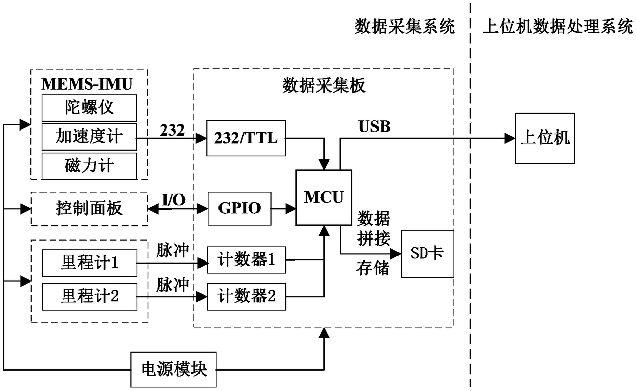
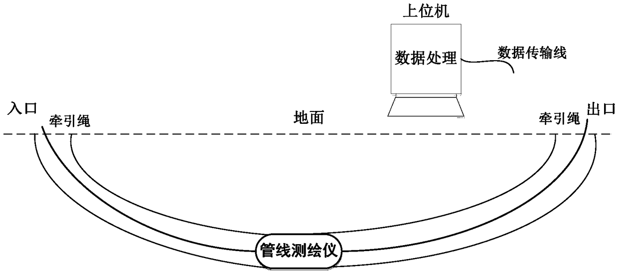
[0042] according to figure 1 and figure 2 , The pipeline surveyor walks in the pipeline under the traction of the traction rope, detects the three-dimensional information of the pipeline, and after the measurement is completed, the collected data is handed over to the host computer for processing.

[0043] The whole system is divided into two subsystems, the upper computer data processing system and the data acquisition system.

[0044] The upper computer data processing system adopts a PC that is convenient for on-site work. After the measurement is completed, the data stored in the SD card is received through USB communication, and the corresponding data processing program is run for processing, and finally the three-dimensional image of the measurement trajectory is obtained.

[0045] In the data acquisition system, the pi...


PUM


Abstract

The invention discloses an underground pipeline trajectory detection system based on inertia measurement. The system is composed of two sub systems. A data acquisition system is loaded in a mechanicalbody to form a pipeline surveying instrument which comprises an MEMS-IMU, a speedometer, a built-in lithium battery and a data acquisition plate. The MEMS-IMU is used for providing a real-time gesture information of the surveying instrument, the speedometer is used for providing real-time journey information of the surveying instrument, the data acquisition plate receives sensor data and stores the data in an SD card, and after measurement, the stored data is uploaded to an upper computer through a USB interface. An upper computer data processing system obtains a real-time gesture angle through inertial navigation calculation and information infusion, carries out dead reckoning by combining the journey information to obtain a walking trajectory of the surveying instrument in the pipeline,and corrects the trajectory by means of the inlet / outlet position of the pipeline to obtain a tested pipeline trajectory. The measuring method is of autonomy, is not affected by external environmentand buried depth of pipelines, and by using non-excavation means, the system does not need ground operations, so that the system is economic, efficient and environment-friendly.

Description

technical field [0001] The invention belongs to the field of track detection of underground pipelines, and in particular relates to a track detection system and method for underground pipelines based on inertial measurement. Background technique [0002] Underground pipelines are one of the most important infrastructures in cities. Since the reform and opening up, the national economy has grown rapidly and urban construction is in full swing. However, the construction of underground pipeline facilities has not been given enough attention. The planning of pipelines is not strong. The performance is poor, the pipelines are criss-crossed, and they are fragmented. Urban expansion and infrastructure construction are increasingly complex and dense, bringing a series of potential problems. Any problem with underground pipelines such as water, electricity, and communication will threaten the public safety of the city. The construction and improvement of underground pipeline geograp...

Claims


Application Information

Patent Timeline
IPC IPC(8): G01C21/16
CPCG01C21/005G01C21/165
Inventor 刘锡祥司马健杨文强许广富郭小乐
Owner SOUTHEAST UNIV
Learn More