
Optical current transformer anti-interference method and optical current transformer system

A current transformer, optical technology, used in the measurement of current/voltage, voltage/current isolation, instruments, etc., can solve problems such as poor anti-vibration reliability

Active Publication Date: 2019-03-19
XUJI GRP +3
View PDF9 Cites 1 Cited by
  • Summary
  • Abstract
  • Description
  • Claims
  • Application Information

AI Technical Summary

Problems solved by technology

[0006] The object of the present invention is to provide an optical current transformer anti-jamming method and an optical current transformer system to solve the problem of poor anti-vibration reliability in the way of changing the hardware structure

Method used


Image

  • Optical current transformer anti-interference method and optical current transformer system
  • Optical current transformer anti-interference method and optical current transformer system
  • Optical current transformer anti-interference method and optical current transformer system

Examples


Embodiment Construction

[0064] Optical current transformer system embodiment

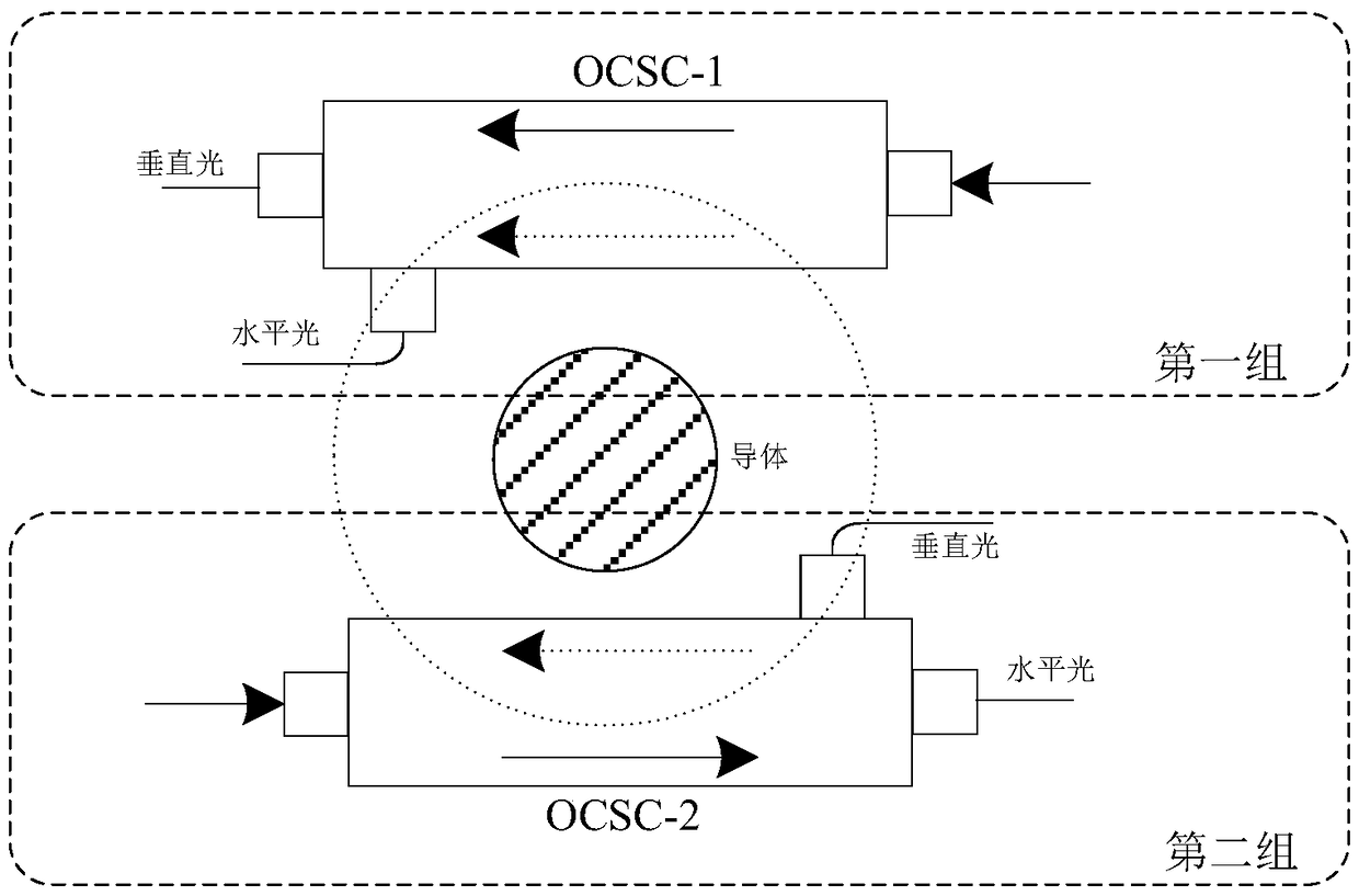
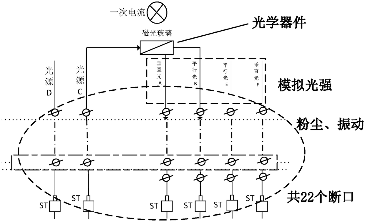
[0065] This embodiment provides an optical current transformer system, including two current detection devices, one is an optical current transformer. This embodiment takes a representative optical current transformer as an example. Of course, other types of optical current transformers can also be used. Current Transformer, figure 1 It is a schematic diagram of the detection principle of an optical fiber current transformer, such as figure 2 As shown, each fiber optic current transformer has multiple simulated optical breaks; the other is a current detection module. Of course, the two current detection devices detect the current signal of the same line, so that the following current signal replacement mechanism can be realized. Among them, the current detection module is a conventional current detection device, such as a conventional current transformer, which can be specifically an internal LPCT part (low power coil)....


PUM


Abstract

The invention relates to an optical current transformer anti-interference method and an optical current transformer system, wherein a current detection module is arranged; the optical current transformer and the current detection module detect current signals of the same line; when the optical current transformer vibrates, and the current signal detected by the optical current transformer replacedwith the current signal detected by the current detection module to output the current signal detected by the current detection module. The system ensures that the system works normally when the optical current transformer vibrates, eliminates the influence caused by vibration interference, avoids the misoperation of a relay protection device, and is very suitable for a power system, particularlya high-voltage grade system. According to the scheme, the structure of the optical current transformer is not modified, so that the detection precision of the optical current transformer is not influenced; and the modification is made from the source, no matter what vibration the optical current transformer is subjected to, the current detection module can output normal current signals in a modeof replacing the optical current transformer, so that the detection precision is improved.

Description

technical field [0001] The invention relates to an optical current transformer anti-interference method and an optical current transformer system. Background technique [0002] The optical current transformer (OCT) based on the Faraday magneto-optic effect has always been the mainstream of optical current sensing technology. It measures the current indirectly by measuring the line integral of the magnetic field intensity caused by the measured current i. According to the Faraday magneto-optic Effect, when linearly polarized light passes through the medium under the action of an external magnetic field parallel to its propagation direction, its polarization angle is deflected, and its magnitude is proportional to the primary current. That is, the primary current is indirectly measured by measuring the polarization angle. [0003] In optical sensing, the measurement principle based on the Faraday magneto-optic effect is one of the most effective and practical methods for meas...

Claims


Application Information

Patent Timeline
Patent Type & Authority Applications(China)
IPC IPC(8): G01R15/24G01R19/165
CPCG01R15/245G01R19/16533
Inventor 李磊尹明田萍郑业兵刘晓霞魏艳伟丁志龙
Owner XUJI GRP
Learn More