Method for measuring weight moment of turbine blade of gas turbine

A turbine blade and measurement method technology, applied in force/torque/work measuring instruments, measuring devices, instruments, etc., can solve the problems that the weight moment cannot be accurately measured and cannot be directly measured, and the measurement method is simple and practical. The effect of low probability of error and high accuracy

Inactive Publication Date: 2018-12-07
华瑞(江苏)燃机服务有限公司
View PDF8 Cites 1 Cited by
  • Summary
  • Abstract
  • Description
  • Claims
  • Application Information

AI Technical Summary

Problems solved by technology

Usually, the weight moment is calculated by multiplying the mass M of the blade by the distance from its center of gravity to the center of rotation, where the distance from the center of gravity to the center of rotation is divided into the distance L1 from the center of gravity of the blade to the installation position and the distance R from the installation position to the center of rotation during actual measurement. , the latter distance value R can be directly measured, but the distance from the center of gravity to the installation position is difficult to measure accurately, because the position of the center of gravity of the blade will change according to its size and weight, and it cannot be directly measured, so the weight moment cannot be obtained. Realize precise measurement calculation

Method used


Image

  • Method for measuring weight moment of turbine blade of gas turbine
  • Method for measuring weight moment of turbine blade of gas turbine

Examples


no. 1 example

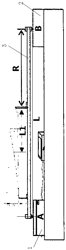
[0025] Such as figure 1 As shown, the method for measuring the weight moment of a turbine blade of a gas turbine disclosed by the present invention is mainly aimed at fast and accurate measurement of blades of a small gas turbine, and specifically includes the following steps:

[0026] Step 1. Place an electronic scale 1 and a boss 2 respectively on a horizontal plane with a certain distance between them, and the upper surface of the electronic scale and the boss are located on the same horizontal plane;

[0027] Step 2. Set up the two ends of the blade placing platform 3 on the electronic scale and the boss respectively, the supporting point with the electronic scale is A, and the supporting point with the boss is B, and the placing platform is in a horizontal state at this time;

[0028] Step 3. Adjust the value displayed on the electronic scale to zero to ensure that the weight value of the subsequent weighing does not include the weight of the placement platform, and then ...

no. 2 example

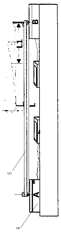
[0031] Such as figure 2 As shown, the method for measuring the weight moment of a turbine blade of a gas turbine disclosed by the present invention is mainly aimed at fast and accurate measurement of blades of heavy-duty gas turbines. Due to the increase in size and weight of heavy-duty gas turbine blades, the radius of gyration Also increase, if also adopt the form of first embodiment to measure, just need to place the length of platform to increase, in order to ensure the measuring range of electronic scale, what usually adopts for placing platform is the aluminum alloy material processing with lighter quality, If its length increases, it will cause bending deformation during the measurement process, which will affect the measurement accuracy. Therefore, for the measurement of the central gas turbine impeller, the method of this embodiment is adopted, which specifically includes the following steps:

[0032] Step 1. Place the two electronic scales 4 respectively on a horizo...


PUM


Abstract

The invention discloses a method for measuring the weight moment of a turbine blade of a gas turbine. The method comprises the steps of (1) placing an electronic scale and a boss on a horizontal surface, (2 ) erecting two ends of a blade placement table on the electronic scale and the boss, wherein a support point with the electronic scale is A, and a support point with the boss is B, (3) installing the turbine blade on the placement table, reading a value WA of the electronic scale at this time and measuring a vertical distance L between the support point A and the support point B at the sametime, and (4) converting the weight moment according to a torque balance principle, wherein a counterclockwise direction torque W1*(R+L1) is equal to a clockwise direction torque WA*L with the support point B as a rotation point, and therefore, M1=W1*(R+L1)=WA*L is obtained. According to the method, the torque is converted by using the principle of torque balance, a value that cannot be accurately measured is substituted with the value that can not be accurately measured, and therefore, the fast and accurate measurement operation of the weight moment is achieved.

Description

technical field [0001] The invention relates to a measuring method, in particular to a measuring method for the weight moment of a gas turbine blade. Background technique [0002] Turbomachinery is a dynamic fluid machine with blades, which is characterized by the high-speed rotating motion of the rotor equipped with blades. When the fluid (gas / liquid) flows through the passage between the blades, the force generated between the blades and the fluid Interaction, in order to realize the conversion of energy. The most important part of turbomachinery is the rotating element (rotor / impeller), which is installed on the turbine shaft and has blades evenly arranged along the circumference. The specific working principle is as follows: the energy of the fluid is converted into Kinetic energy, when the fluid flows through the rotor, the fluid impacts the blades, pushing the rotor to rotate, thereby driving the turbine shaft to rotate, and then the turbine shaft drives other machine...

Claims


Application Information

Patent Timeline
Patent Type & Authority Applications(China)
IPC IPC(8): G01L5/00
CPCG01L5/00
Inventor 李振
Owner 华瑞(江苏)燃机服务有限公司
Why Eureka
Try Eureka