Forward interpolation method for angle sensor and rotary encoder

A rotary encoder and angle sensor technology, applied in the field of semiconductors, can solve the problems of not meeting the requirements of accuracy and real-time performance

Active Publication Date: 2018-12-07
SHANGHAI MAIGEEN MICROELECTRONICS CO LTD
View PDF6 Cites 7 Cited by
  • Summary
  • Abstract
  • Description
  • Claims
  • Application Information

AI Technical Summary

Problems solved by technology

However, the sensor sampling sensing part currently used cannot meet such high precision and real-time requirements.

Method used


Image

  • Forward interpolation method for angle sensor and rotary encoder
  • Forward interpolation method for angle sensor and rotary encoder
  • Forward interpolation method for angle sensor and rotary encoder

Examples


Embodiment 1

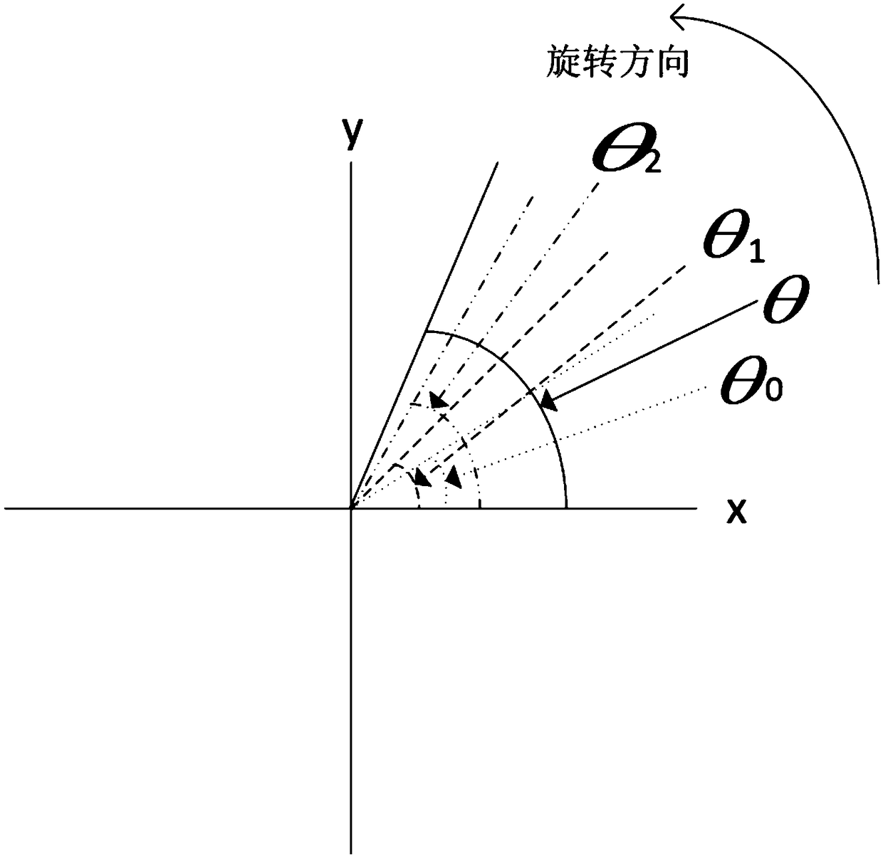
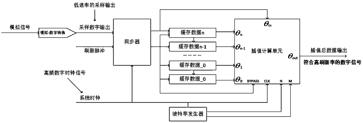
[0091] see figure 1 , the present invention discloses a forward interpolation method of an angle sensor and a rotary encoder based on the principle of discrete rotational inertia. Angle changes within. The method includes: according to the inertia theorem of rigid body motion, assuming that the rigid body rotates in a short period of time to follow the principle of uniform acceleration motion (corresponding to the following step S1); on the basis of the angular position information obtained at the latest several sampling moments Calculate to obtain the angular velocity and angular acceleration value of the predicted starting position (corresponding to the following step S2); according to the angular information, angular velocity information and angular acceleration information of the starting position, perform forward interpolation prediction calculation under the requirements of the output frequency (corresponding to The following steps S3 and S4).

[0092] Described method...

Embodiment 2

[0124] The difference between this embodiment and Embodiment 1 is that in this embodiment, the present invention discloses a forward interpolation method of an angle sensor and a rotary encoder based on the principle of discrete rotational inertia. The angle information of the object at the time is used to predict the angle change of the object in the next period of time. The method includes: according to the inertia theorem of rigid body motion, assuming that the rigid body rotates in a relatively short period of time to follow the principle of uniform acceleration motion; calculate on the basis of the angular position information obtained at the latest several sampling moments, and obtain the predicted starting position The angular velocity and angular acceleration values; according to the angle information, angular velocity information and angular acceleration information of the starting position, the forward interpolation prediction calculation is performed under the requir...


PUM


Abstract

The invention discloses a forward interpolation method for an angle sensor and a rotary encoder. The method comprises the steps of prejudging an angle where a current mechanical structure is located before a next sensor sample is output; according to different application scenes and requirements on prediction precisions, selecting outputs of different numbers of sampling inductors as input conditions of an interpolation algorithm; and when two sampling outputs are used as interpolation basic values, simplifying a uniformly accelerated motion into a uniform motion. According to the forward interpolation method for the angle sensor and the rotary encoder provided by the invention, the limitation of a low-speed sampling induction unit is effectively broken through, the valid data refresh of the angle sensor and the rotary encoder is greatly improved, and the real-time angle information of a rotor is provided in time; with the algorithm, the high-frequency noise caused by an error betweenan interpolation prediction and an actual sampling result is avoided so that the outputs are more smooth.

Description

technical field [0001] The invention belongs to the technical field of semiconductors, relates to an angle sensor and a rotary encoder, in particular to a forward interpolation method of the angle sensor and the rotary encoder based on the principle of discrete rotational inertia. Background technique [0002] Angle sensors and rotary encoders are important carriers for measuring angle information during the rotation of various mechanical structures. At present, it is widely used in various fields, such as industrial equipment control cars, smart home, smart multimedia equipment, Internet of Things technology, etc. [0003] Based on the current mainstream sensing elements (such as Hall sensor type, magnetoresistive sensor type, electromagnetic induction sensor type, etc.), the angle judgment method is mainly to obtain the current angular position of the device through the direction and strength of the magnetic field. [0004] Due to the increasing requirements for the accur...

Claims


Application Information

Patent Timeline
Patent Type & Authority Applications(China)
IPC IPC(8): G06F17/17
CPCG06F17/17Y02P90/02
Inventor 朱剑宇孙毅
Owner SHANGHAI MAIGEEN MICROELECTRONICS CO LTD
Why Eureka
Try Eureka