

Finite element model correction method based on sensitivity analysis
A technology of sensitivity analysis and model correction, applied in special data processing applications, instruments, electrical digital data processing, etc., can solve problems such as inaccurate finite element modeling and simulation
Inactive Publication Date: 2018-12-07
SHENYANG INST OF AUTOMATION - CHINESE ACAD OF SCI
View PDF5 Cites 22 Cited by
- Summary
- Abstract
- Description
- Claims
- Application Information
AI Technical Summary
Problems solved by technology
[0005] Aiming at the deficiencies of the prior art, the present invention provides a finite element model correction method based on sensitivity analysis, which uses a small amount of data obtained from structural tests to correct the finite element model to obtain a more accurate finite element model and solves the problem of finite element Inaccurate problem of modeling and simulation
Method used
View moreImage
Smart ImageViewing Examples

Examples
Embodiment
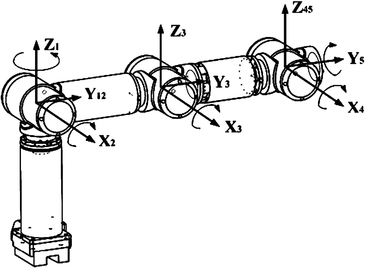
[0040] The invention corrects the finite element model based on the sensitivity analysis for the structure of the five-joint mechanical arm.
Login to View More PUM
 Abstract
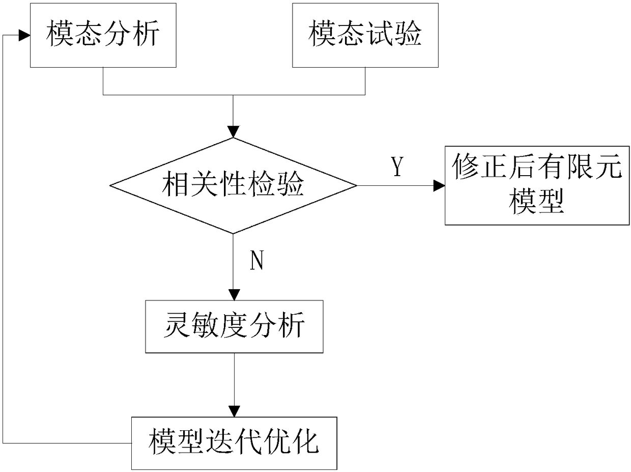
The invention relates to a finite element model correction method based on sensitivity analysis. According to the method, solid modeling is performed on an assembly in three-dimensional software, a modal test is performed on an assembly model through a modal test system, an assembly finite element simulation model is established by the adoption of pre-processing software and post-processing software, modal analysis solving is performed through finite element analysis software, correlation checking is performed on a modal test result and a modal simulation analysis result through LMS.VirtualLabsimulation analysis software, modal sensitivity analysis is performed, parametric variables sensitive to modal frequency are found out, and finite element model fundamental frequency is matched withmodal test fundamental frequency through optimization iteration. Compared with a physical test, the simulation analysis technology has many advantages such as low cost and a short cycle; and within asimulation result error allowed range, the simulation analysis result can serve as a reference basis for vibration characteristic analysis, so that the method has important reference value for relevant test work.
Description
technical field [0001] The invention relates to the field of finite element model correction of complex assemblies, in particular to a finite element model correction method based on sensitivity analysis. Background technique [0002] With the rapid development of CAE technology in the field of industrial manufacturing, through finite element simulation analysis, the vibration characteristics of the mechanism are studied, the weak parts in the structural design are pointed out, and the optimization scheme can be proposed to avoid the occurrence of resonance in the mechanism during work. At the same time, finite element analysis is the most widely used numerical analysis method in the field of modern engineering, and its reliability has been widely verified. Through finite element simulation analysis, the number of physical tests can be reduced to achieve the purpose of saving costs, evaluating the rationality of configuration, reducing risks, improving product quality, and s...
Claims
Login to View More Application Information
Patent Timeline
 IPC IPC(8): G06F17/50G01M7/00
CPCG01M7/00G06F30/17G06F30/23
Inventor富佳骆海涛刘广明轿利闯
OwnerSHENYANG INST OF AUTOMATION - CHINESE ACAD OF SCI