Supercharge Your Innovation With Domain-Expert AI Agents!

A synchronous rectifier control chip and ac-dc system

A technology of synchronous rectifier tube and control chip, which is applied in control/regulation system, output power conversion device, DC power input conversion to DC power output, etc. It can solve the problems of power tube damage, inductor current backflow, spike voltage, etc. , to achieve the effect of reducing risk, improving reliability, and avoiding common phenomena

Active Publication Date: 2020-09-15
SHENZHEN WINSEMI MICROELECTRONICS
View PDF6 Cites 0 Cited by
  • Summary
  • Abstract
  • Description
  • Claims
  • Application Information

AI Technical Summary

Problems solved by technology

The commonality of the above-mentioned primary and secondary sides will cause the secondary inductance current to flow back and the current of the power tube on the primary side to have a large spike. The more serious the backflow, the bigger the spike
This serious spike current will affect the reliability of the power tube for long-term work. What is more serious is that the excessive spike current will cause a spike voltage to appear at the drain end of the power tube on the primary side, which will further cause the power tube to directly damage
[0005] It can be seen that for the primary side chip that needs to be compatible with the PEAK-LOAD function, there is a lot of room for improvement in the current synchronous rectifier control method

Method used


Image

  • A synchronous rectifier control chip and ac-dc system
  • A synchronous rectifier control chip and ac-dc system
  • A synchronous rectifier control chip and ac-dc system

Examples


Embodiment Construction

[0042]The present invention provides a synchronous rectifier control chip and an AC-DC system. In order to make the purpose, technical solution and effect of the present invention clearer and clearer, the present invention will be further described in detail below with reference to the accompanying drawings and examples. It should be understood that the specific embodiments described here are only used to explain the present invention, not to limit the present invention.

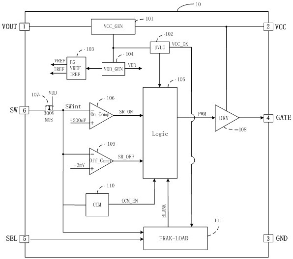
[0043] see image 3 A synchronous rectifier control chip provided by the present invention includes a chip body and a circuit arranged inside the chip body, and the circuit inside the chip body includes a VCC power generation circuit 101, a VCC undervoltage comparator 102, a reference voltage current Generating circuit 103, internal power supply VDD generating circuit 104, logic circuit 105, synchronous rectifier turn-on comparator 106, high-voltage MOS transistor 107, drive circuit 108, synchronous rectifie...


PUM


Abstract

The present invention discloses a control chip of a synchronous rectifier and an AC-DC system. The control chip comprises a VCC power source generation circuit, a VCC undervoltage comparer, a reference voltage and current generation circuit, an internal power source VDD generation circuit, a logic circuit, a synchronous rectifier turn-on comparer, a high-voltage MOS tube, a drive circuit, a synchronous rectifier turn-off comparer, a CCM working mechanism circuit and a PEAK-LOAD working mechanism circuit. The VCC power source generation circuit is connected with the VCC undervoltage comparer, the internal power source VDD generation circuit and the drive circuit, the internal power source VDD generation circuit is connected with the grid of the high-voltage MOS tube, and the VCC undervoltage comparer is connected with the logic circuit and the PEAK-LOAD working mechanism circuit. The control chip of a synchronous rectifier and the AC-DC system detect the voltage signals of the drain ofthe synchronous rectifier, VCC signals and SEL pin signals to achieve control for the PEAK-LOAD working mechanism circuit to effectively avoid a primary side power tube common phenomenon, and are compatible with a primary side drive chip with a PEAK-LOAD function to greatly reduce the system risk and improve the reliability.

Description

technical field [0001] The invention relates to the field of AC-DC switching power supplies, in particular to a control chip of a synchronous rectifier tube and an AC-DC system. Background technique [0002] As switching power supplies have increasingly stringent requirements for efficiency, using synchronous rectification MOS tubes to replace freewheeling Schottky diodes has become a mainstream technology trend. [0003] However, when the synchronous rectification MOS tube controller does not communicate directly with the main switch signal of the primary side, how to effectively avoid the simultaneous conduction phenomenon of the power tube of the primary side and the synchronous rectifier tube of the secondary side (common to the primary and secondary sides) becomes a key technology. [0004] For primary-side chips without PEAK-LOAD function, the synchronous rectification controller technology currently on the market is relatively mature, and there are no special technica...

Claims


Application Information

Patent Timeline
Patent Type & Authority Patents(China)
IPC IPC(8): H02M1/08H02M7/217H02M3/335
CPCH02M1/08H02M3/33592H02M7/217Y02B70/10
Inventor 白文利宋利军
Owner SHENZHEN WINSEMI MICROELECTRONICS
Features
  • R&D
  • Intellectual Property
  • Life Sciences
  • Materials
  • Tech Scout
  • Unparalleled Data Quality
  • Higher Quality Content
  • 60% Fewer Hallucinations
Learn More