Synchronous rectification driving circuit of flyback circuit

A technology of flyback circuit and driving circuit, which is applied in the direction of electrical components, adjusting electric variables, output power conversion devices, etc., can solve the problems of complex circuit, main switch tube and synchronous rectifier tube in common, and achieve simple circuit structure, drive Effects of stable voltage and cost reduction

Active Publication Date: 2009-10-07
BEIJING SUPLET +1
View PDF0 Cites 8 Cited by
  • Summary
  • Abstract
  • Description
  • Claims
  • Application Information

AI Technical Summary

Problems solved by technology

[0004] In view of this, the present invention is to provide a synchronous rectification driving circuit for a flyback circuit, so as to solve the problems of complicated circuit and common use of the main switching tube and the synchronous rectifying tube in the above-mentioned driving mode.

Method used


Image

  • Synchronous rectification driving circuit of flyback circuit
  • Synchronous rectification driving circuit of flyback circuit

Examples


Embodiment Construction

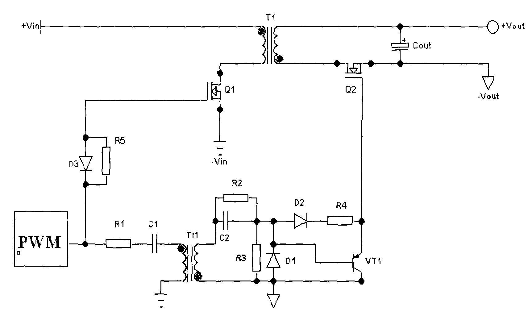
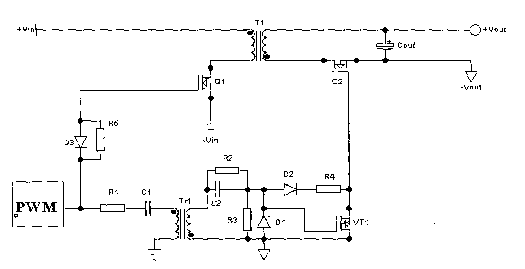
[0016] The present invention will be further described below in conjunction with the accompanying drawings and embodiments. Such as figure 1 As shown, the flyback circuit includes a flyback circuit and a drive circuit, and the flyback circuit includes a main switching tube Q1, a main transformer T1, a synchronous rectifying tube Q2 and an output capacitor Cout.

[0017] In the driving circuit, the PWM driving signal passes through the resistor R1 connected to the same-named end of the primary side of the driving transformer Tr1, the capacitor C1 and the resistor R2 connected to the opposite-named end of the secondary side of Tr1, and the capacitor C2; the cathode of the diode D2 passes through the resistor R4 and The gate of the synchronous rectifier Q2 is connected, and the anode of D2 is connected with C2 to form the gate charging circuit of the synchronous rectifier Q2; the base of the PNP transistor VT1 is connected to the anode of D2, and the emitter and collector are res...


PUM


Abstract

The invention discloses a synchronous rectification driving circuit of a flyback circuit, which has simple structure, easy realization, high efficiency and small volume. The gate-level driving circuit of the secondary edge synchronous rectifying tube Q2 comprises a capacitor C2, resistors R2, R3 and R4, diodes D1 and D2, and a PNP triode VT1, and a driving transformer Tr1 realizes the isolation and transmission of primary side PWM driving signals. The invention uses few discrete elements for forming the driving circuit, thus realizing that the driving voltage is kept to be relatively stable within the wide input voltage range, and avoiding the common-pass phenomenon of a main switching tube Q1 and a synchronous rectifying tube Q2. The invention improves the efficiency of a converter and enhances the reliability of the circuit.

Description

technical field [0001] The invention relates to a DC / DC power supply circuit, in particular to a synchronous rectification drive circuit used in a flyback circuit. Background technique [0002] The flyback converter circuit is widely used in low-power isolated power supplies because of its simple circuit structure, fewer components, and low cost. At present, the power supply used in the communication field is more and more widely used to output low voltage and high current. If the traditional diode rectification is still used, the loss on the rectifier diode will be very large. To maintain the high efficiency of power conversion, mainly use Secondary side synchronous rectification technology, because the conduction loss of MOSFET is very small. The most critical aspect of synchronous rectification technology is the drive mode. At present, there are generally two modes: self-drive or external drive. [0003] Although the structure of the self-driven driving method is simple...

Claims


Application Information

Patent Timeline
Patent Type & Authority Applications(China)
IPC IPC(8): H02M3/28H02M3/335
Inventor 蔡宇翔杜永生
Owner BEIJING SUPLET
Why Eureka
Try Eureka