Vacuum emulsifying device for cosmetic production

A technology of vacuum emulsification and cosmetics, applied in mixers with rotating stirring devices, transportation and packaging, chemical instruments and methods, etc., can solve problems such as inconsistent feeding, emulsifier addition, product specification deviation, etc., and achieve the dosage ratio Precise, slowing effect of flow velocity

Inactive Publication Date: 2018-12-11
沈旭源
View PDF0 Cites 1 Cited by
  • Summary
  • Abstract
  • Description
  • Claims
  • Application Information

AI Technical Summary

Problems solved by technology

[0002] Cosmetic emulsification device is a kind of equipment that can process cosmetics and convert its raw materials from liquid to emulsion shape. However, when the existing equipment is processed, the staff often add emulsifiers externally. The emulsified raw materials loaded are different, which makes it difficult for the staff to add emulsifiers according to the loading amount when adding emulsifiers, resulting in inconsistent additions, resulting in deviations in the specifications of the processed products. When it is in a closed space, it needs to be in a high temperature state during the stirring and emulsification process, so that the moisture in the liquid raw material is evaporated and gasified, and the air pressure in the equipment is increased, which leads to the discharge. Under the influence of air pressure, the raw material is strongly pushed to stamp the discharge pipe. If this is done for a long time, it is easy to cause deformation and damage to the discharge pipe.

Method used


Image

  • Vacuum emulsifying device for cosmetic production
  • Vacuum emulsifying device for cosmetic production
  • Vacuum emulsifying device for cosmetic production

Examples


Embodiment

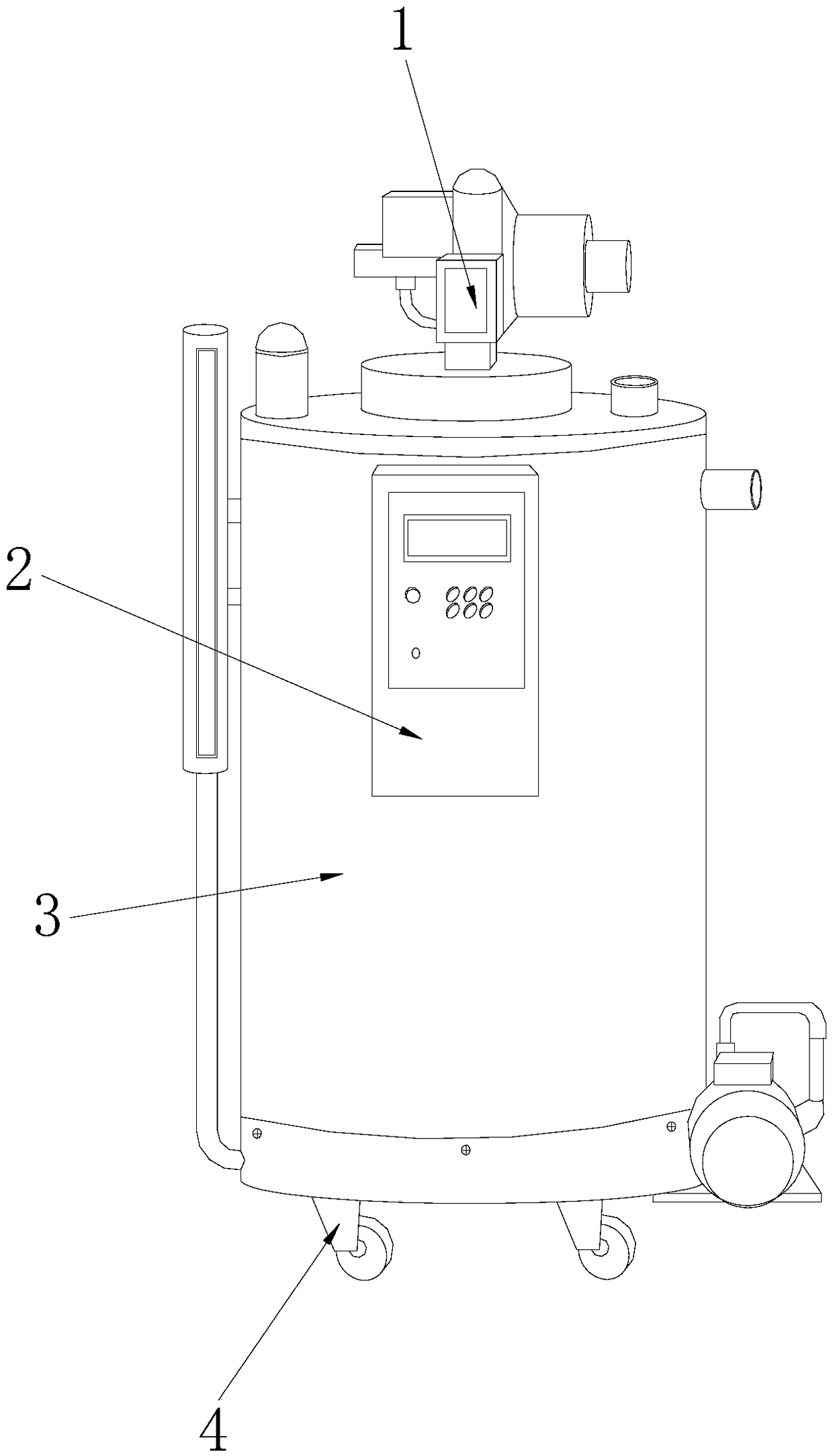
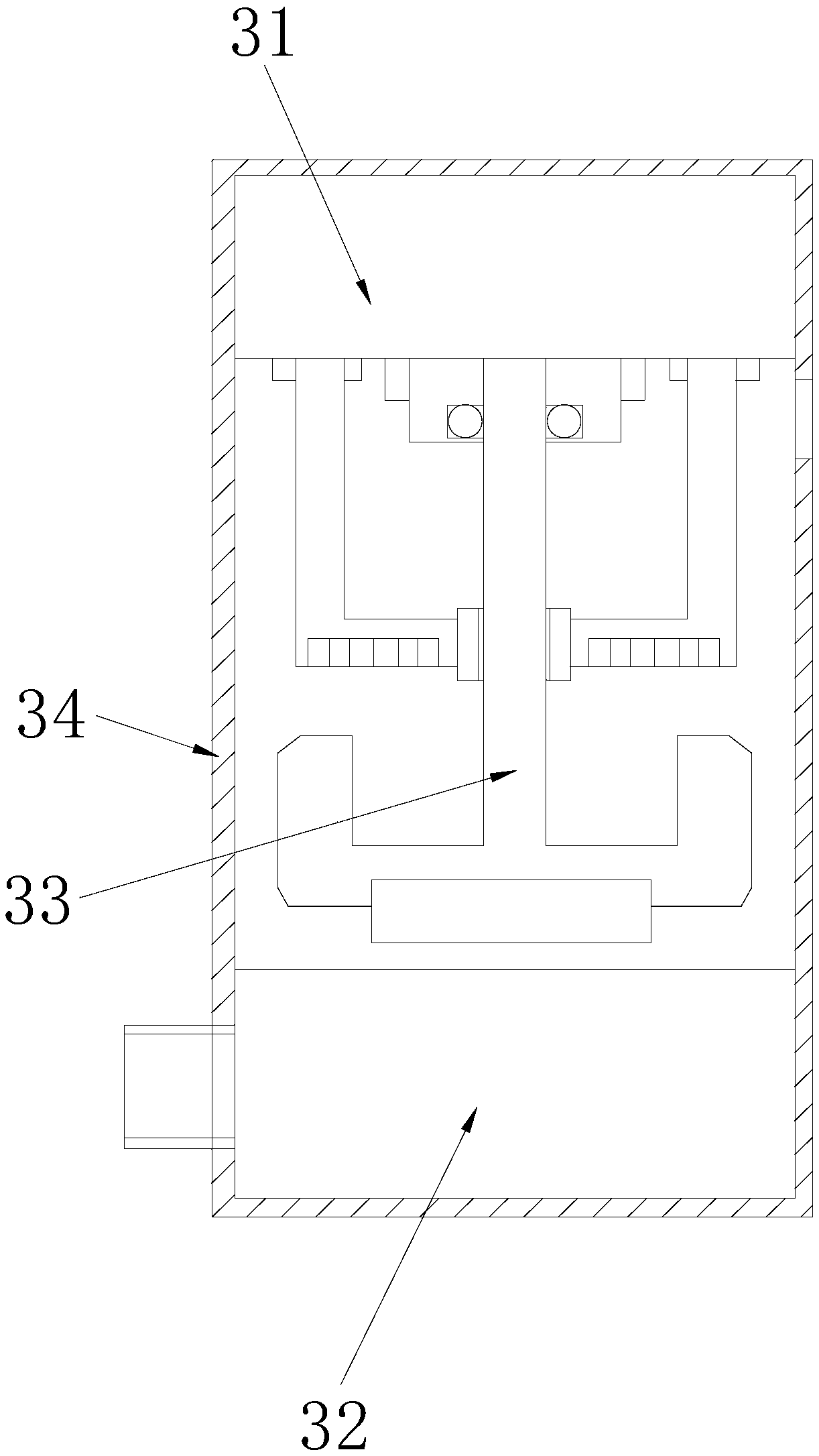
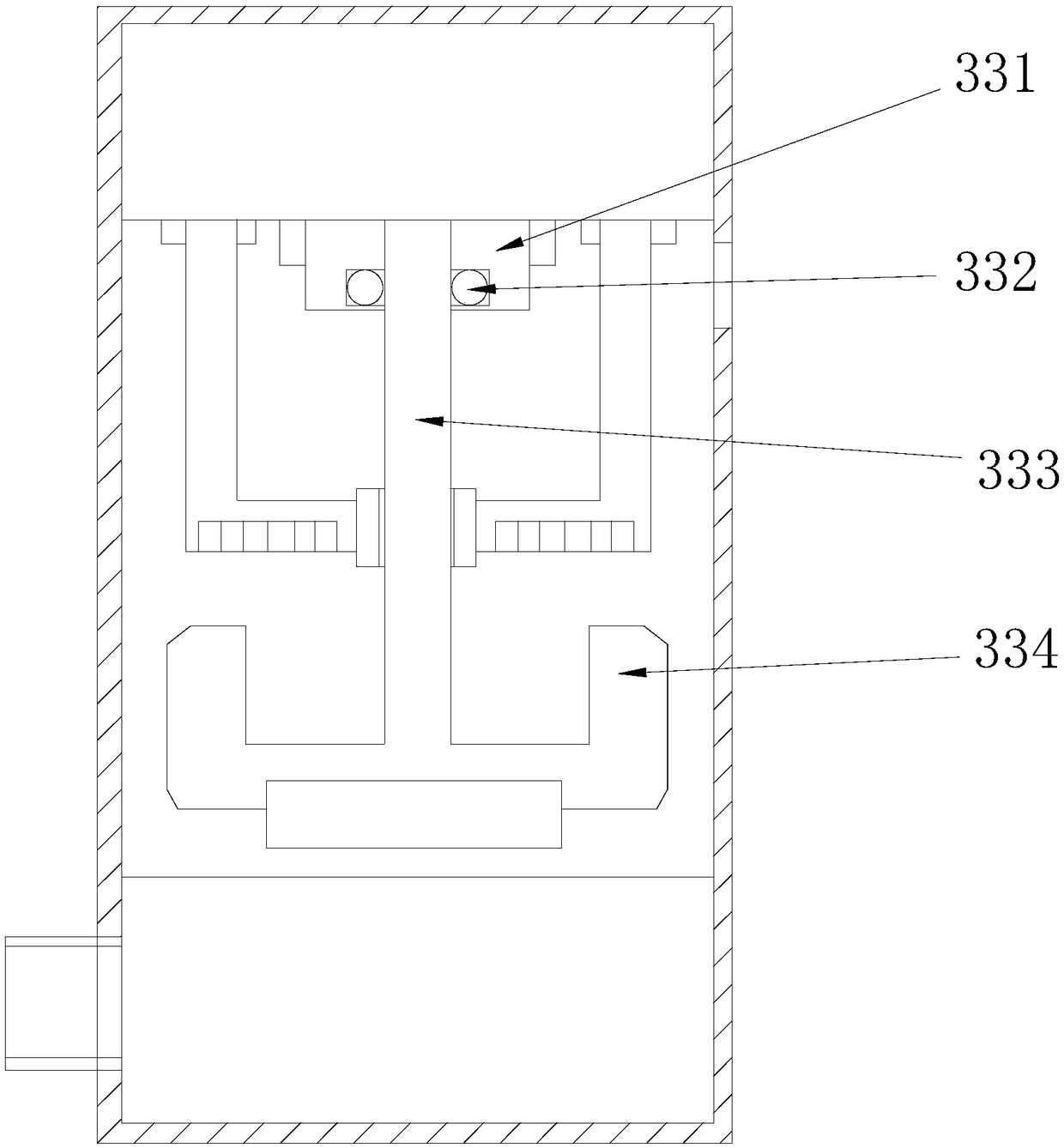
[0027] see Figure 1-Figure 8, the present invention provides a vacuum emulsification device for the production of cosmetics, its structure includes a motor 1, a controller 2, a tank body 3, and a roller 4, the bottom end of the motor 1 is welded to the top end of the tank body 3, and the The controller 2 is arranged at the front end of the tank body 3, and the top end of the roller 4 is welded to the bottom end of the tank body 3. The tank body 3 includes a liquid filling mechanism 31, a liquid discharge mechanism 32, a stirring mechanism 33, and a casing 34. The top of the liquid adding mechanism 31 is welded to the top of the shell 34, the bottom of the liquid discharge mechanism 32 is welded to the bottom of the shell 34, and the top of the stirring mechanism 33 is vertically embedded in the bottom of the liquid adding mechanism 31 In the middle of the end, the stirring mechanism 33 is located directly above the liquid discharge mechanism 32. The liquid addition mechanism ...


PUM


Abstract

The invention discloses a vacuum emulsifying device for cosmetic production. The vacuum emulsifying device structurally comprises a motor, a controller, a tank body and rolling wheels; the bottom endof the motor is welded to the top end of the tank body; the controller is arranged at the front end of the tank body; the top ends of the rolling wheels are welded to the bottom end of the tank body,and the tank body comprises a liquid feeding mechanism, a liquid discharging mechanism, a stirring mechanism and a shell; and the top end of the liquid feeding mechanism is welded to the top end of the shell. According to the vacuum emulsifying device, part of the structure is improved, so that quantitative emulsifier is added into the raw materials according to the liquid level height of added liquid, so that the addition proportion is more accurate, and therefore the phenomenon that the specification of a same product is different due to the fact that the proportion is different by manuallyadding the emulsifier can be effectively avoided, meanwhile, in the discharging process, flow-dividing speed reduction is carried out on a discharging pipeline through a flow-dividing buffering method, and the phenomena that the emulsifier in a machine body is rapidly discharged at the moment when a discharge port is opened, and then strong impact force is generated to extrude and damage the machine body due to the fact that the air pressure generated in the machining process extrudes a finished product can be avoided.

Description

technical field [0001] The invention relates to the field of cosmetic emulsification devices, in particular to a vacuum emulsification device for cosmetic production. Background technique [0002] Cosmetic emulsification device is a kind of equipment that can process cosmetics and convert its raw materials from liquid to emulsion shape. However, when the existing equipment is processed, the staff often add emulsifiers outside. The emulsified raw materials loaded are different, which makes it difficult for the staff to add emulsifiers according to the loading amount when adding emulsifiers, resulting in inconsistent additions, resulting in deviations in the specifications of the processed products. When it is in a closed space, it needs to be in a high temperature state during the stirring and emulsification process, so that the moisture in the liquid raw material is evaporated and gasified, and the air pressure in the equipment is increased, which leads to the discharge. Un...

Claims


Application Information

Patent Timeline
Patent Type & Authority Applications(China)
IPC IPC(8): B01F7/18B01F13/00B01F13/06B01F15/00B01F15/02B01F15/04B01F3/08
CPCB01F23/43B01F23/41B01F27/1122B01F27/90B01F33/501B01F33/70B01F35/2112B01F35/714B01F35/717B01F35/754B01F35/88B01F2101/21
Inventor 沈旭源
Owner 沈旭源
Why Eureka
Try Eureka