Drilling, grinding and spraying all-in-one machine for transmission shaft machining

A transmission shaft and integrated machine technology, applied in the direction of manufacturing tools, other manufacturing equipment/tools, etc., can solve the problems of poor processing effect, low processing efficiency, corrosion and damage of the transmission shaft, etc., to ensure the consistency of processing and improve the prevention Corrosion effect, effect of improving processing efficiency

Inactive Publication Date: 2018-12-11
杭州佰牛科技有限公司
View PDF0 Cites 8 Cited by
  • Summary
  • Abstract
  • Description
  • Claims
  • Application Information

AI Technical Summary

Problems solved by technology

[0002] In precision mechanical transmission, the transmission precision is often required to be very high. With the increase of the number of transmission stages, the requirements for the manufacturing precision and service life of the transmission parts also increase. The transmission shaft is an important component of the mechanical transmission mechanism. The quality of production and processing directly affects the use effect of the transmission mechanism. However, most of the existing transmission shaft end face grinding and surface drilling are processed by manual operation equipment. Not only the processing efficiency is low, but also the processing accuracy of the transmission shaft is difficult to be guaranteed. The processing effect is poor, and there is no protective layer on the surface of the existing transmission shaft. In some harsh working environments, the transmission shaft is easily corroded and damaged, which affects the service life of the transmission mechanism. In order to better meet the processing needs, we The processing equipment has been developed and improved

Method used


Image

  • Drilling, grinding and spraying all-in-one machine for transmission shaft machining
  • Drilling, grinding and spraying all-in-one machine for transmission shaft machining
  • Drilling, grinding and spraying all-in-one machine for transmission shaft machining

Examples


Embodiment 1

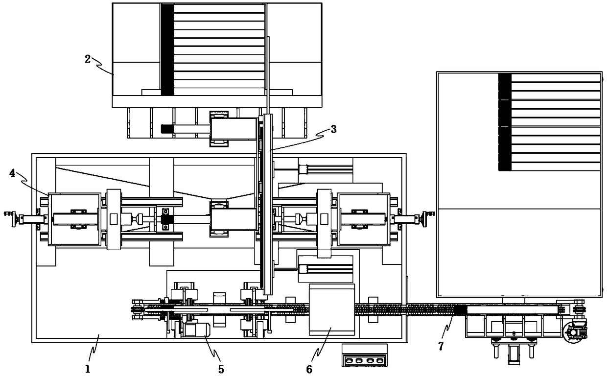
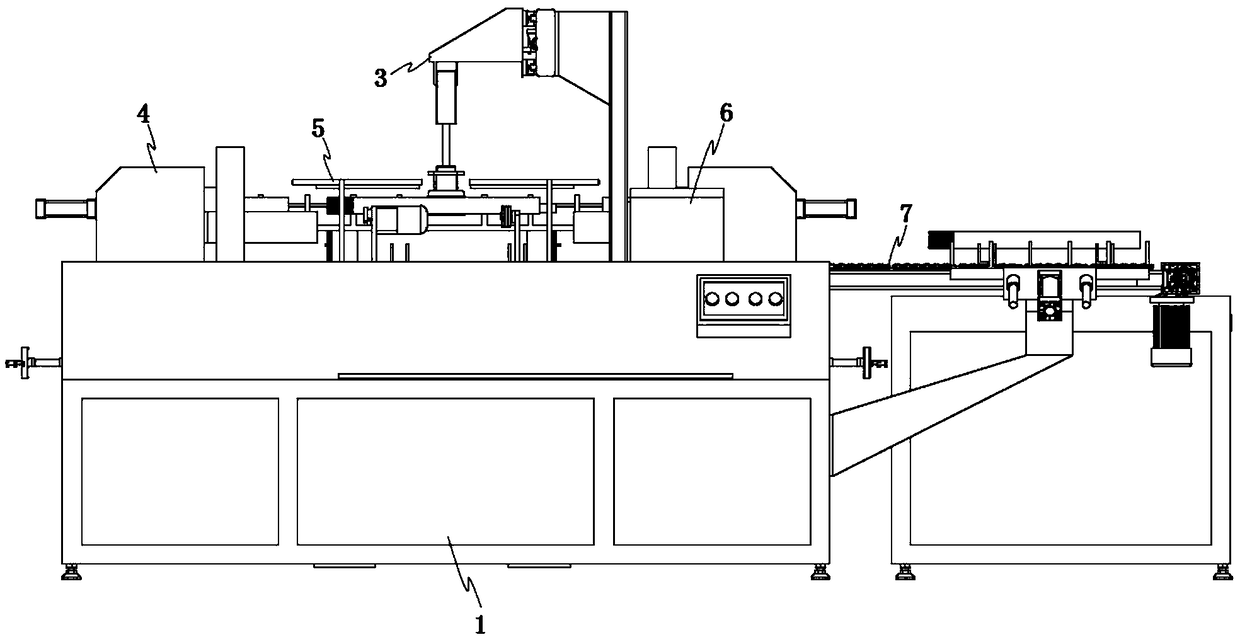
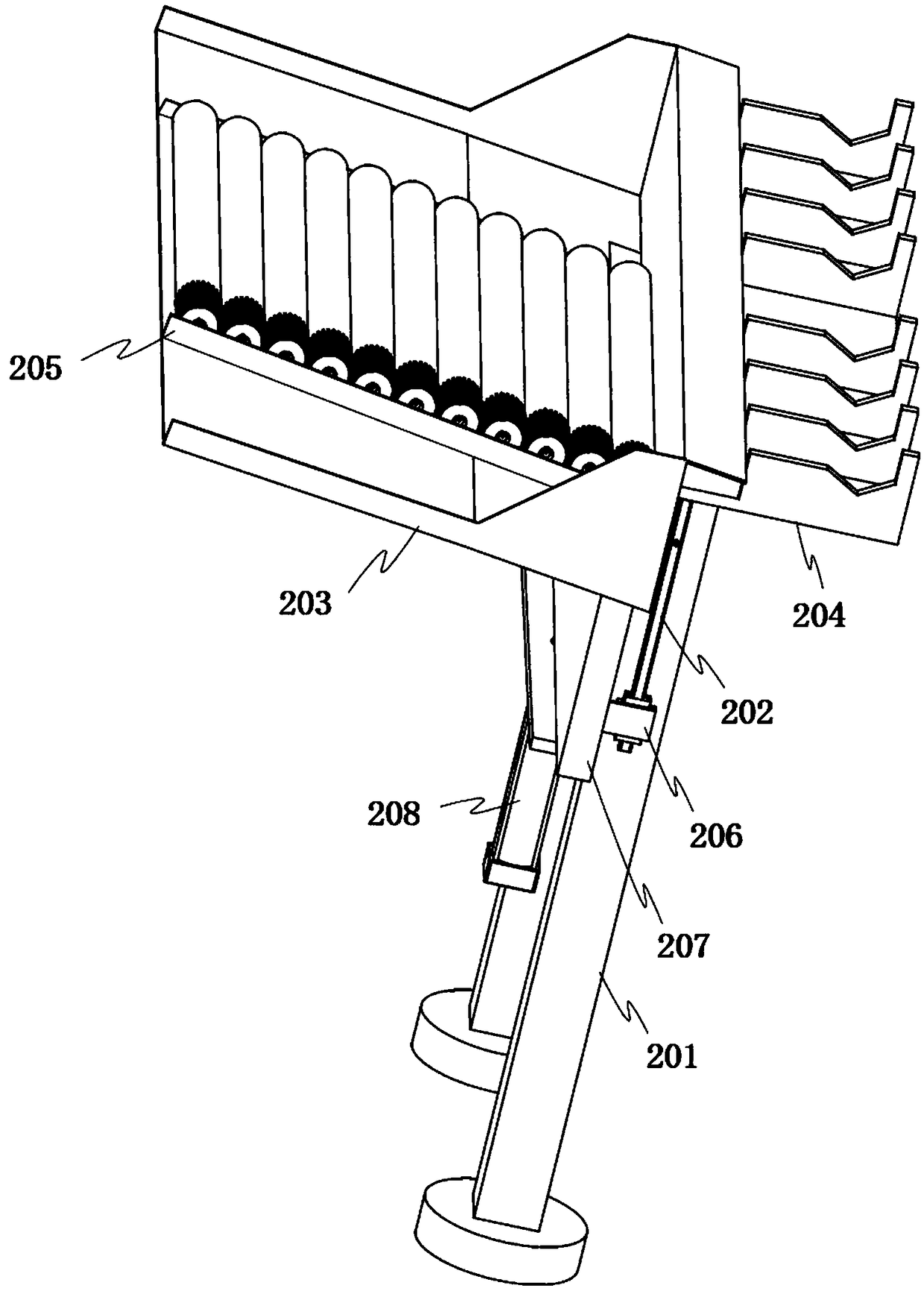
[0036] Before the machining of this integrated machine, the transmission shafts are manually placed one by one along the limit groove plate 205 in the transmission shaft storage groove frame 203 of the transmission shaft input mechanism 2, and then the input drive cylinder 208 is started, and the input drive cylinder 208 Drive the jacking plate 207 to move up along the vertical slide rail 202, and the drive shaft in the drive shaft storage tank frame 203 is lifted by the jacking plate 207, and the drive shaft finally rolls into the drive shaft support row from the upper end of the jacking plate 207. On the board 204, at the same time input the drive cylinder 208 to drive the jacking plate 207 back to the original position, then start the horizontal displacement drive cylinder 304 on the transmission shaft transport mechanism 3, and the horizontal displacement drive cylinder 304 drives the installation slider 305 along the parallel slide rail II 303 Slide to the top of the trans...

Embodiment 2

[0038] When the all-in-one machine grinds and drills the transmission shaft, it first rotates the manual rotation screw 404, and drives the sliding box 402 to slide along the parallel slide rail I 401 according to the length of the transmission shaft, and adjusts the position between the transmission shaft and the frame 405 to facilitate the transmission. Shaft placement, then start the grinding drive motor 407, drive the grinding wheel 408 to rotate by the grinding drive motor 407, start the upper drive cylinder 409 at the same time, drive the grinding drive motor 407 to move forward horizontally by the upper drive cylinder 409, and make the rotating grinding wheel 408 move forward Grind the end face of the transmission end, start and drive the lower driving cylinder 410 on the sliding box 402 at the same time, the lower driving cylinder 410 drives the sliding plate frame 403 to move forward along the parallel slide rail I401 to both ends of the transmission shaft, and then sta...

Embodiment 3

[0040] After the end surface of the transmission shaft is polished and the surface is drilled, start the horizontal displacement driving cylinder 304 on the transmission shaft handling mechanism 3, and the horizontal displacement driving cylinder 304 drives the installation slider 305 to slide along the parallel slide rail II 303 to the upper part of the transmission shaft, and then Start the vertical displacement drive cylinder 306, drive the clamping drive cylinder 307 to move down to the position of the transmission shaft by the vertical displacement drive cylinder 306, then start the clamping drive cylinder 307, and drive the clamping block 308 to clamp the transmission shaft by the clamping drive cylinder 307. The shaft is driven upward by the vertical displacement driving cylinder 306, and the horizontal displacement driving cylinder 304 is driven to slide along the parallel slide rail II 303, and the transmission shaft is moved to the gap position between the supporting r...


PUM


Abstract

The invention relates to a drilling, grinding and spraying all-in-one machine for transmission shaft machining. The drilling, grinding and spraying all-in-one machine for transmission shaft machiningcomprises a mounting table body, wherein a transmission shaft carrying mechanism, a grinding and drilling mechanism, a spraying mechanism and a baking chamber are arranged on the mounting table body;a transmission shaft input mechanism is arranged on the side, close to the transmission shaft carrying mechanism, of the mounting table body; and a transmission shaft output mechanism is arranged onthe side, close to the spraying mechanism, of the mounting table body. Integrated machining of end face grinding, side wall surface drilling and surface rustproof paint spraying of a transmission shaft is realized, the machining method of grinding and drilling the transmission shaft by operating equipment manually in the past is replaced, not only is the machining efficiency of the transmission shaft improved, but also the machining consistency of the transmission shaft is guaranteed, the accuracy is ensured, meanwhile, rustproof paint is also sprayed on the surface of the transmission shaft,the corrosion protection effect of the transmission shaft is improved, and the service life of the transmission shaft is long.

Description

technical field [0001] The invention relates to the technical field of transmission shaft processing equipment, in particular to a drilling, grinding and spraying integrated machine for processing transmission shafts. Background technique [0002] In precision mechanical transmission, the transmission precision is often required to be very high. With the increase of the number of transmission stages, the requirements for the manufacturing precision and service life of the transmission parts also increase. The transmission shaft is an important component of the mechanical transmission mechanism. The quality of production and processing directly affects the use effect of the transmission mechanism. However, most of the existing transmission shaft end face grinding and surface drilling are processed by manual operation equipment. Not only the processing efficiency is low, but also the processing accuracy of the transmission shaft is difficult to be guaranteed. The processing ef...

Claims


Application Information

Patent Timeline
Patent Type & Authority Applications(China)
IPC IPC(8): B23P23/04B23P23/06
CPCB23P23/04B23P23/06
Inventor 王毅军
Owner 杭州佰牛科技有限公司
Why Eureka
Try Eureka