Prefoaming machine for foam pad plate preparation

A technology for pre-foaming and foam pads, applied in the field of pre-foaming machines for the preparation of foam pads, can solve the problems of low foaming efficiency, inconvenient pressure adjustment, insufficient safety, etc. novel effect

Active Publication Date: 2018-12-11
浏阳市华诚泡沫塑料制品有限公司
View PDF9 Cites 2 Cited by
  • Summary
  • Abstract
  • Description
  • Claims
  • Application Information

AI Technical Summary

Problems solved by technology

[0003] For above-mentioned situation, in order to overcome the defective of prior art, the present invention provides a kind of pre-expansion machine for foam pad preparation, solves the problem that existing pre-expansion machine is generally low-speed stirring type and relies on slow-speed rotating blade to introduce gas, But the bubble output is small, the foaming efficiency is low, or the high-speed impeller type relies on the high-speed rotating impeller to induce air, but the size of the bubble diameter cannot be controlled, the foam is uneven, and the overall movement is inconvenient, and the pressure adjustment is inconvenient, prone to pressure deviation, not enough safety issue

Method used


Image

  • Prefoaming machine for foam pad plate preparation
  • Prefoaming machine for foam pad plate preparation
  • Prefoaming machine for foam pad plate preparation

Examples


Embodiment 1

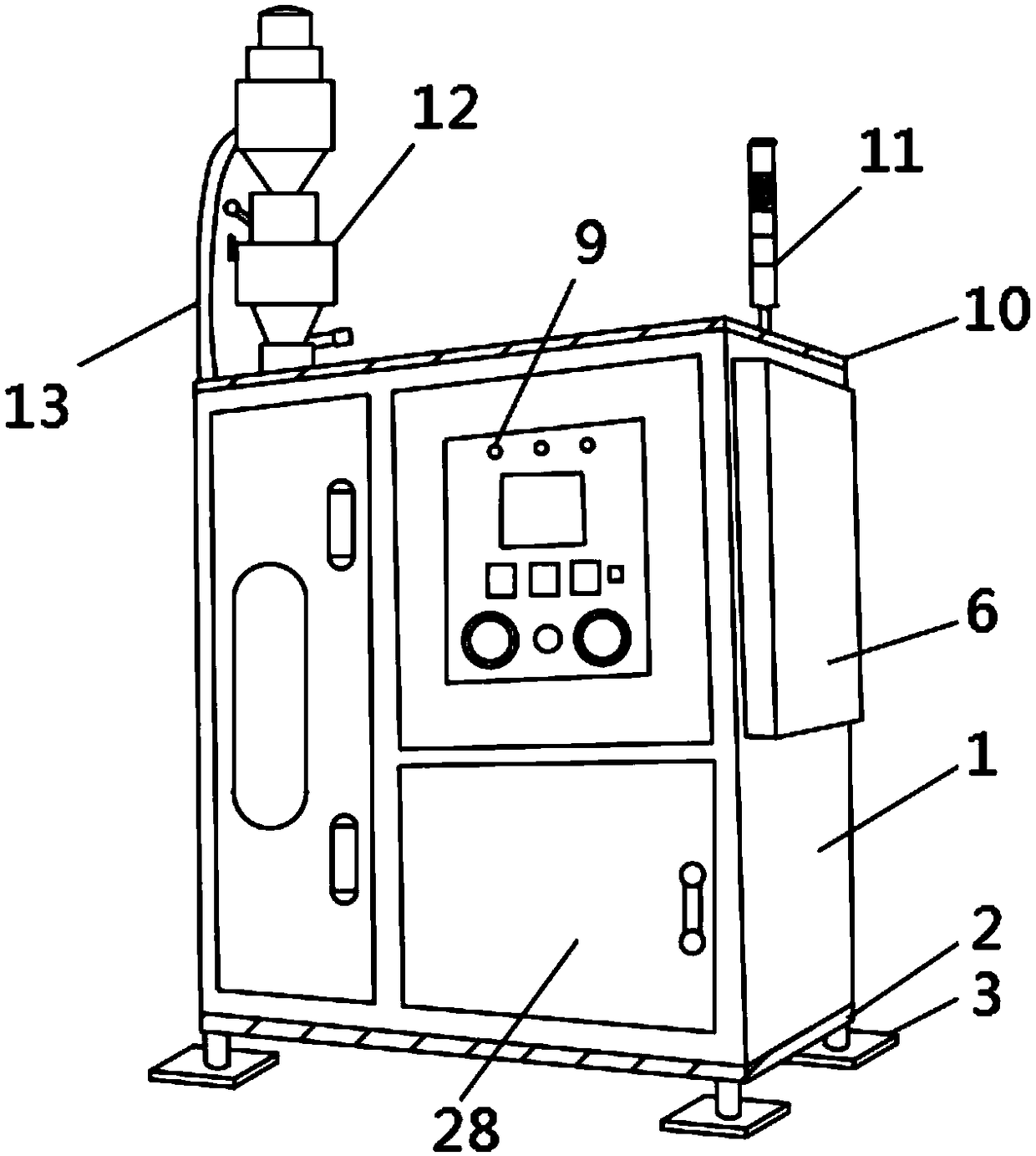
[0019] Embodiment one, by figure 1 , figure 2 , image 3 and Figure 4 Given, the present invention includes a pre-foaming machine body 1, the bottom end of the pre-foaming machine body 1 is provided with a bottom fixing plate 2, the bottom end of the bottom fixing plate 2 is provided with a support foot 3, and the bottom end of the bottom fixing plate 2 is close to The position of the support foot 3 is provided with a groove 4, the inside of the bottom fixed plate 2 is located at the top of the groove 4, and a hydraulic cylinder 5 is arranged, and the bottom end of the hydraulic cylinder 5 is located inside the groove 4, and a first support rod 6 is arranged. The bottom end of a support rod 6 is provided with a roller 7, and the roller 7 is connected with the first support rod 6 through a roller support frame 8. One side of the pre-foaming machine body 1 is provided with a control board 9, and the input end of the control board 9 It is electrically connected to the mains,...

Embodiment 2

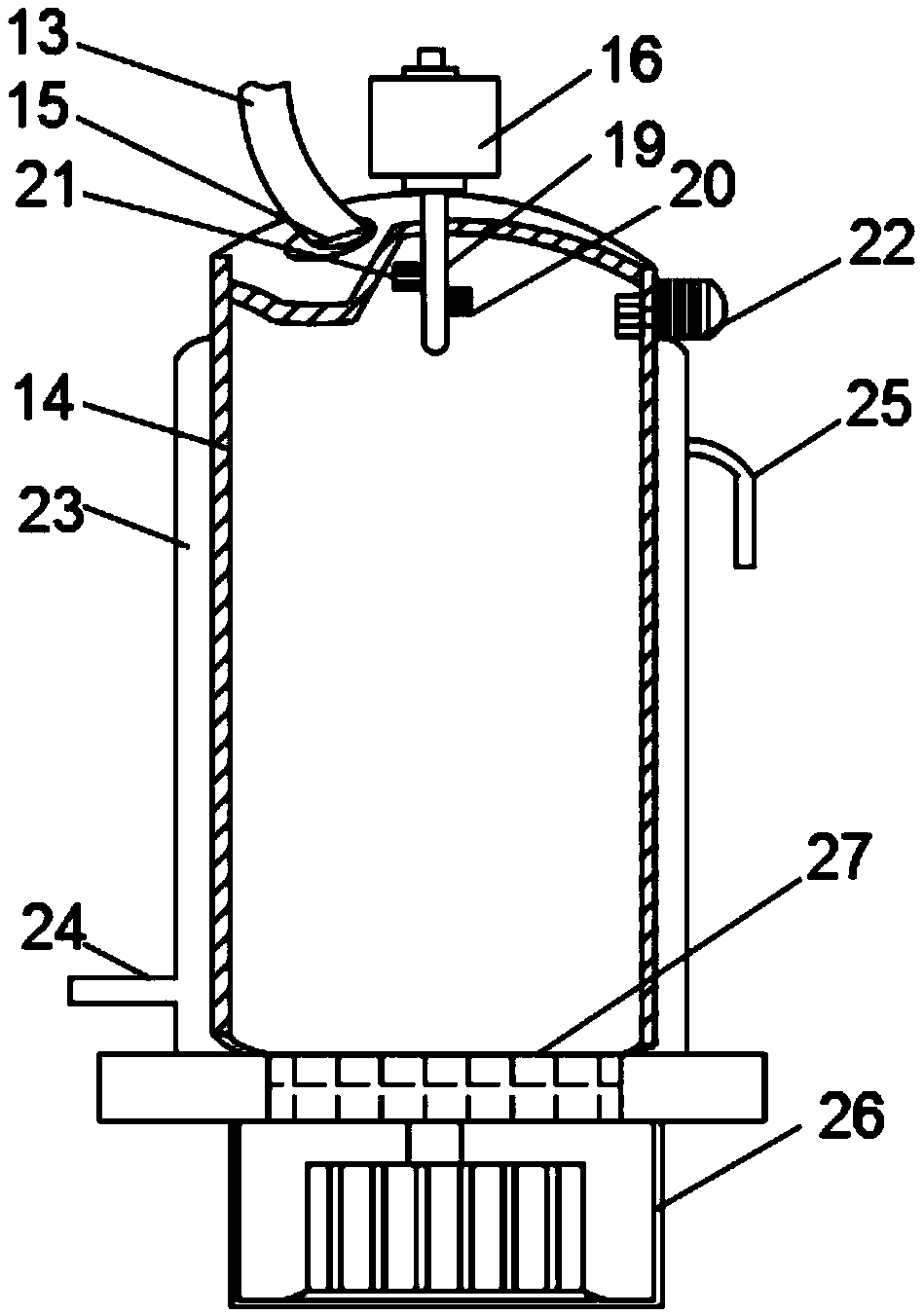
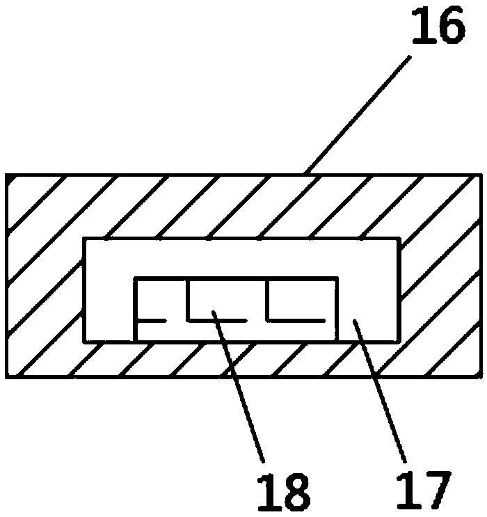
[0021] Embodiment two, on the basis of embodiment one, by figure 2 and image 3 Given, the outside of the foaming tank 14 is provided with a U-shaped heating tube 23, one end of the U-shaped heating tube 23 is provided with a liquid inlet 24, the other end of the U-shaped heating tube 23 is provided with a liquid outlet 25, and the bottom of the foaming tank 14 A heater 26 is arranged at the top of the heater 26, and a heat conduction plate 27 is arranged on the top of the heater 26. The temperature sensor 21 is electrically connected to the input end of the controller 18, and the output end of the controller 18 is electrically connected to the heater 26. When in use, the liquid inlet 24 Inject hot water into the U-shaped heating pipe 23, and the hot water is exported through the liquid outlet 25, so that the foaming tank 14 can be heated, and the foaming efficiency can be improved. At the same time, the temperature inside the foaming tank 14 can be sensed by the temperature ...

Embodiment 3

[0022] Embodiment three, on the basis of embodiment one, by Figure 5 Provided, one side of the bottom of the pre-foaming machine body 1 is provided with a locker 28, the top inside the locker 28 is provided with a support plate 29, the middle part of the support plate 29 is provided with a partition plate 30, and the two sides of the partition plate 30 Both ends are provided with a first slider 31, the inner wall of the locker 28 and the top of the support plate 29 are provided with a first slide rail 32 at the position corresponding to the first slider 31, and the middle part of the locker 28 is provided with a movable Plate 33, moving plate 33 two ends are all provided with the second slide block 8, and the position place that the inner wall of locker 28 is provided with the second slide block 34 is all provided with the second slide rail 35, when using, through locker 28 , can make the whole have a certain storage function, and the functions are diverse. At the same time, ...


PUM


Abstract

The invention relates to a prefoaming machine for foam pad plate preparation, and solves the problems that the existing prefoaming machine generally belongs to a low-speed stirring type; gas is introduced through low-speed rotation blades; the bubble yield is small; the foaming efficiency is low, or the prefoaming machine belongs to a high-speed impeller type; air is introduced through a high-speed rotation impeller; the bubble diameter size cannot be controlled; the foam is not uniform; meanwhile, the whole moving is inconvenient; the pressure regulation is inconvenient; the pressure deviation can easily occur; the safety is poor. The prefoaming machine comprises a prefoaming machine body, wherein a bottom fixing plate is arranged at the bottom end of the prefoaming machine body; supportfeet are arranged at the bottom end of the bottom fixing plate; grooves are formed in positions, near the support feet, of the bottom end of the bottom fixing plate; a hydraulic cylinder is arranged at the top end, positioned at the groove, inside the bottom fixing plate. The prefoaming machine has the advantages that the structure is novel; the whole can conveniently move; meanwhile, high pressure is used, so that the bubble generating speed is high; the efficiency is high; the bubbles are uniform and fine; the pressure can be guaranteed; meanwhile, the warning on the pressure can be realized; the efficiency is high; safety and reliability are realized.

Description

technical field [0001] The invention relates to the technical field of production of foam pads, in particular to a pre-foaming machine for preparing foam pads. Background technique [0002] Foam pad - also known as foam board, EPS board is a white object formed by heating and pre-expanding in a mold from expandable polystyrene beads containing a volatile liquid foaming agent. It has fine closed cells. Its structural characteristics are mainly used for building walls, roof insulation, composite board insulation, cold storage, air conditioning, vehicle, ship insulation, floor heating, decoration and engraving, etc. The foamable styrene polymer is pre-expanded into foam particles, which requires the use of a pre-expansion machine, and the existing pre-expansion machine is generally a low-speed stirring type that introduces gas by slow-speed rotating blades, but the bubble output Small, low foaming efficiency or high-speed impeller type relies on high-speed rotating impeller to...

Claims


Application Information

Patent Timeline
Patent Type & Authority Applications(China)
IPC IPC(8): B29C44/34B29C44/60B29K25/00B29L7/00
CPCB29C44/34B29C44/3415B29C44/60B29K2025/06B29L2007/002
Inventor 文志美
Owner 浏阳市华诚泡沫塑料制品有限公司
Why Eureka
Try Eureka