
Optical fiber coating paint tank

A coating tank and coating technology, which is applied in the field of optical fiber manufacturing, can solve the problems of newly generated bubbles and easy introduction, and achieve the effects of high utilization rate, stable coating supply, and improved coating quality

Pending Publication Date: 2018-12-11
PNC PROCESS SYSTEMS CO LTD
View PDF0 Cites 2 Cited by
  • Summary
  • Abstract
  • Description
  • Claims
  • Application Information

AI Technical Summary

Problems solved by technology

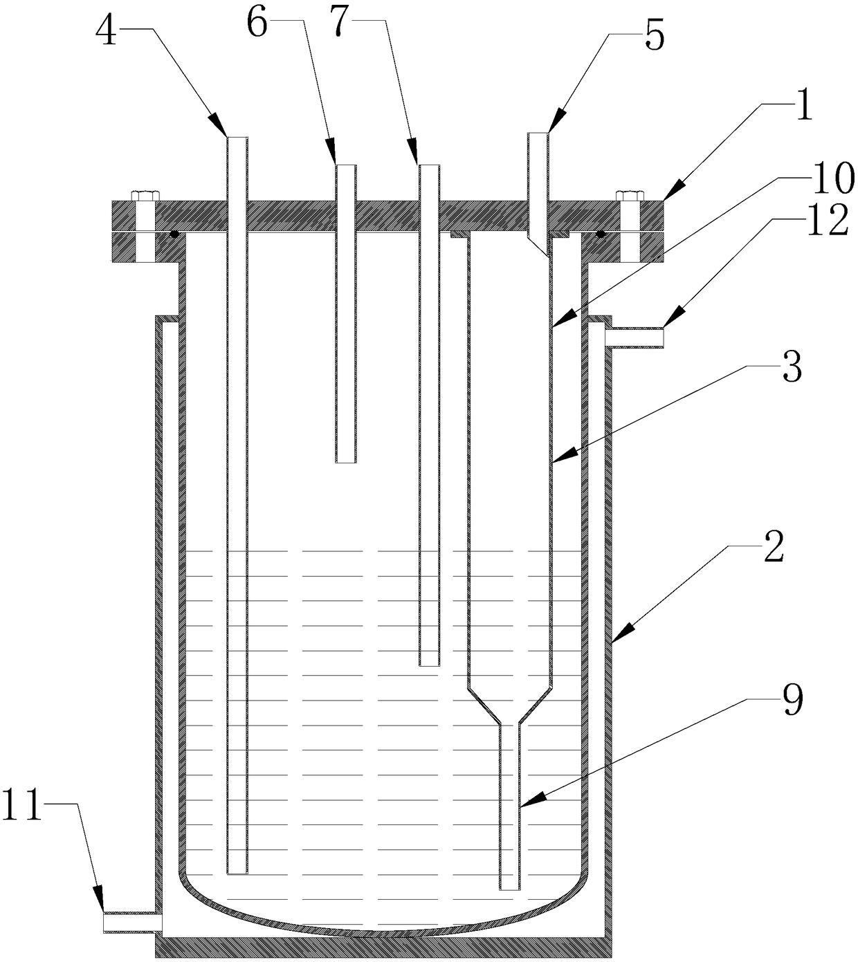
[0005] In view of the deficiencies in the prior art above, the purpose of the present invention is to provide a coating tank for optical fiber coating, aiming to solve the problem that the existing coating tank is easy to introduce or newly generate air bubbles in the process of filling the coating

Method used


Image

  • Optical fiber coating paint tank
  • Optical fiber coating paint tank
  • Optical fiber coating paint tank

Examples


Embodiment Construction

[0019] In order to make the object, technical solution and advantages of the present invention clearer, the present invention will be further described in detail below in conjunction with the accompanying drawings and embodiments. It should be understood that the specific embodiments described here are only used to explain the present invention, not to limit the present invention.

[0020] It should be noted that when an element is referred to as being “fixed on” or “disposed on” another element, it may be directly on the other element or there may be an intervening element at the same time. When an element is referred to as being "connected to" another element, it can be directly connected to the other element or intervening elements may also be present.

[0021] It should also be noted that the orientation terms such as left, right, up, and down in the embodiments of the present invention are only relative concepts or refer to the normal use state of the product, and should ...


PUM


Abstract

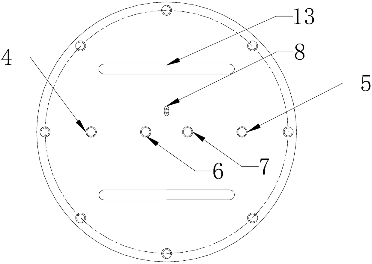
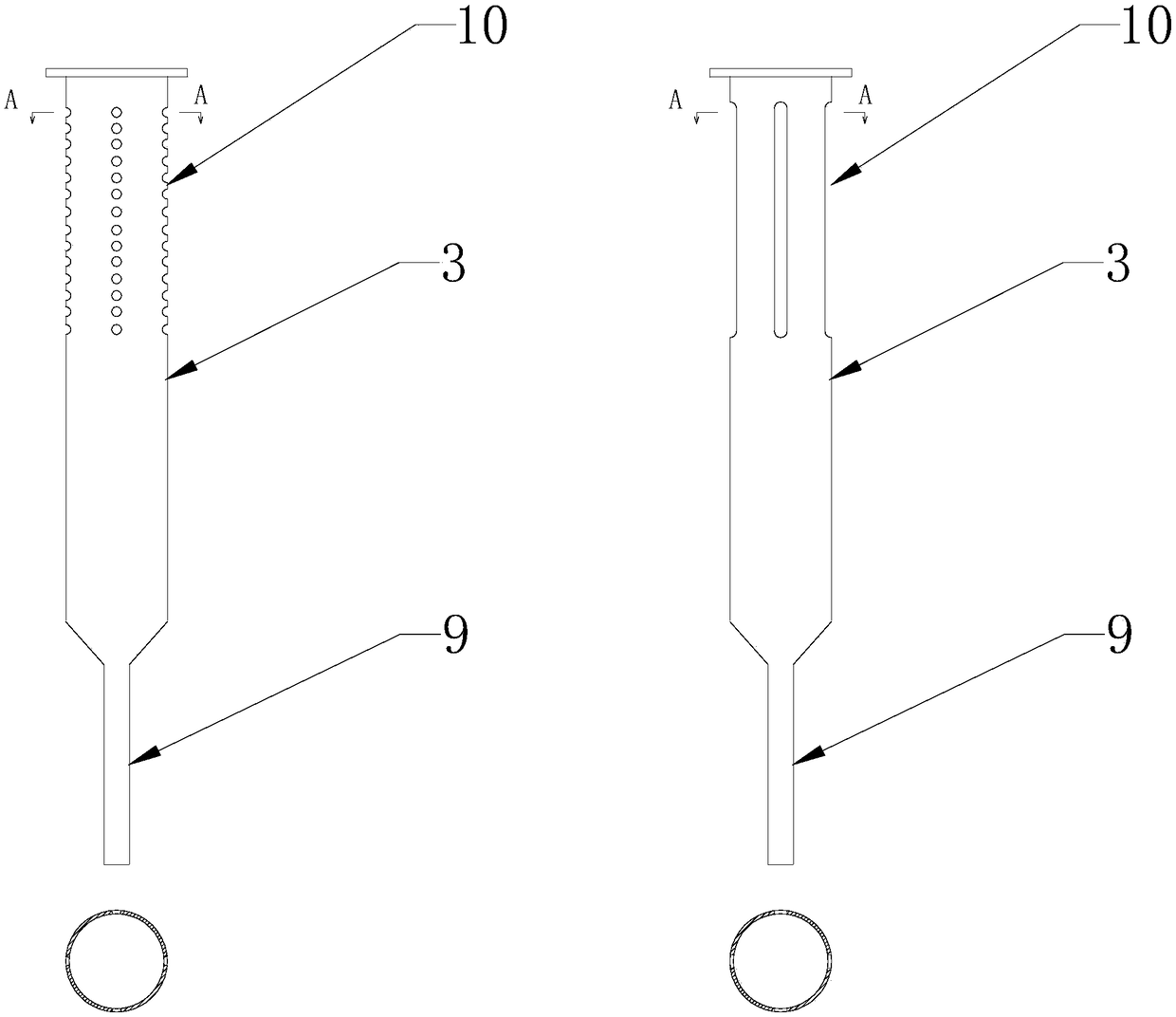
The invention discloses an optical fiber coating paint tank. The optical fiber coating paint tank comprises a paint tank main container and a water jacket container, wherein the paint tank main container is embedded inside the water jacket container, the upper end surface of the paint tank main container is provided with a paint tank handle, and the paint tank main container is sequentially provided with a liquid inlet, a low-level sensor mouthpiece, a compressed air joint and a liquid outlet; the lower end of the liquid inlet is provided with a buffer pipe, the lower end of the buffer pipe isprovided with a guide pipe, and the upper end of the buffer pipe is provided with a breathing port; the upper end surface of the paint tank main container I also provided with the compressed air joint. The optical fiber coating paint tank can avoid being influenced by external paint feeding speed and guide paint to flow into the paint tank main container along the inner and outer walls of the buffer pipe to avoid bubbles due to impact of fluid dropping onto liquid surface; meanwhile, the optical fiber coating paint tank can achieve release of tiny bubbles inside the paint during a flow guiding process to ensure stable paint supply and reduce bubble content.

Description

technical field [0001] The invention relates to the technical field of optical fiber manufacturing, in particular to a coating tank for optical fiber coating. Background technique [0002] In the production process of optical fiber, since the optical fiber drawn from the high-temperature furnace contacts air, it is easy to absorb moisture and dust, which affects the use effect of the optical fiber. Therefore, the coating should be applied immediately after the optical fiber is drawn to protect the optical fiber, so as to avoid the influence of the external environment on the optical fiber. At the same time, the optical fiber coating can also enhance the mechanical strength of the optical fiber and improve the transmission performance of the optical fiber. Therefore, the coating is very important in the production of optical fiber, and it is an important part of the optical fiber. The quality of the coating directly affects the performance of the optical fiber. [0003] In t...

Claims


Application Information

Patent Timeline
Patent Type & Authority Applications(China)
IPC IPC(8): B67D7/02B67D7/06
CPCB67D7/02B67D7/06
Inventor 连海洲薛元吴海华
Owner PNC PROCESS SYSTEMS CO LTD
Learn More