
LED lamp lead wire frame strip electroplating guide frame

A technology of guide frame and lamp lead wire, which is applied in the direction of electrolysis process, electrolysis assembly, contact device, etc., can solve the problems of wear and deformation of LED lamp lead frame belt, and difficulty in adjusting the distance between two brass blocks.

Inactive Publication Date: 2018-12-11
徐百灵
View PDF0 Cites 0 Cited by
  • Summary
  • Abstract
  • Description
  • Claims
  • Application Information

AI Technical Summary

Problems solved by technology

[0002] During the electroplating process of the LED lamp lead frame strip, it is necessary to position the LED lamp lead frame strip in continuous horizontal movement, so that the LED lamp lead frame strip is kept at a fixed height for electroplating, so as to control the electroplating area. The existing The guiding method is to use two pieces of brass blocks with grooves, and the LED light lead frame with both side edges snaps into the grooves of the two brass blocks to move horizontally. During electroplating, the LED light lead frame has brass on both sides. The blocks need to be connected to the electrodes to electroplate the LED lamp lead frame strips, but the distance between the two brass blocks is very difficult to adjust in actual operation. If the distance is too wide, it will easily cause the LED lamp lead frame strips to not be able to connect with the brass. If the distance is too narrow, it will easily cause wear or deformation on both sides of the LED lamp lead frame strip, which will affect the post-processing; therefore, it is necessary to develop a bracket that can automatically guide the LED lamp lead frame strip

Method used


Image

  • LED lamp lead wire frame strip electroplating guide frame
  • LED lamp lead wire frame strip electroplating guide frame
  • LED lamp lead wire frame strip electroplating guide frame

Examples


Embodiment Construction

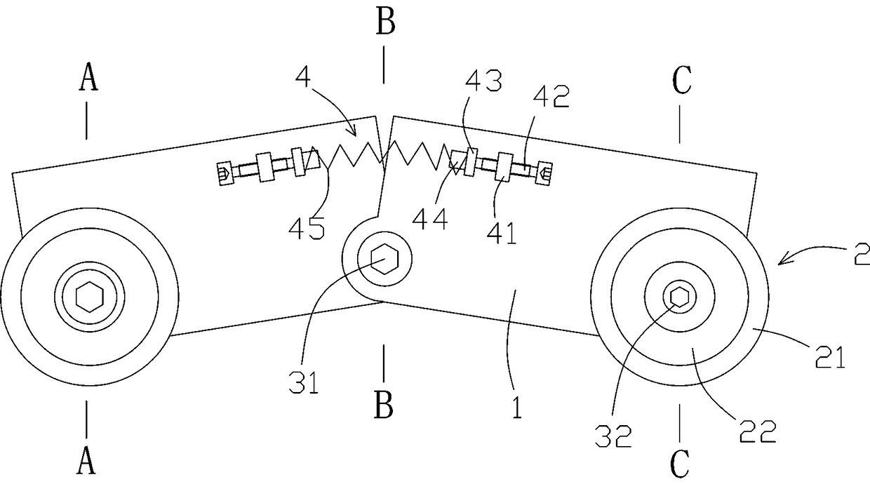
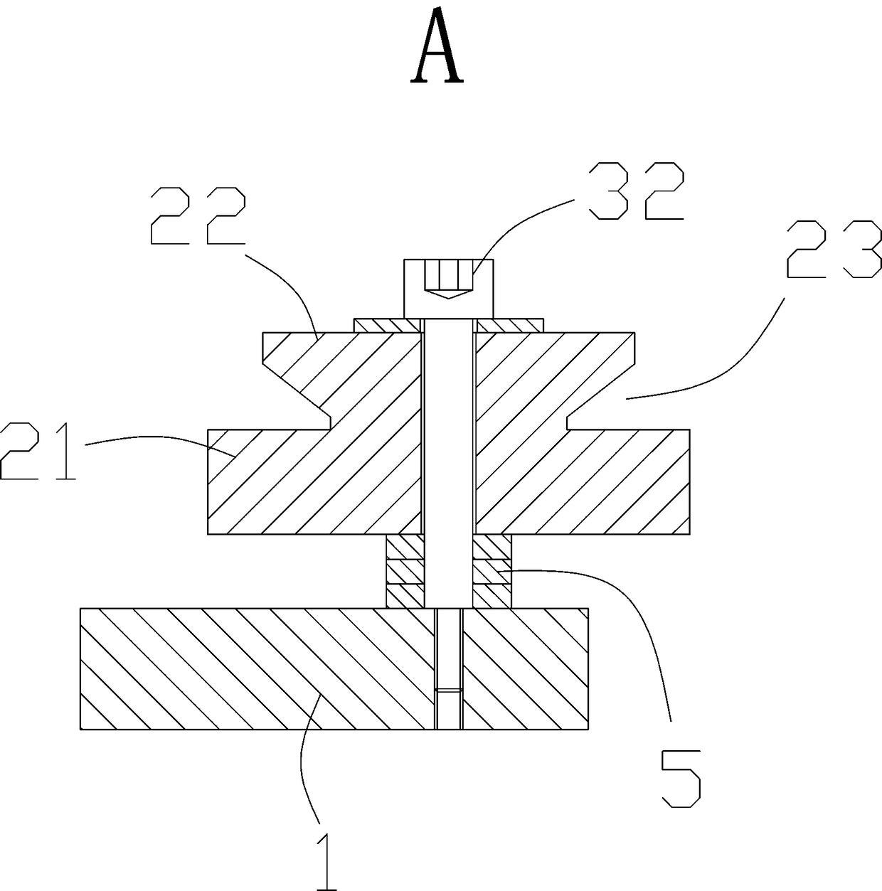
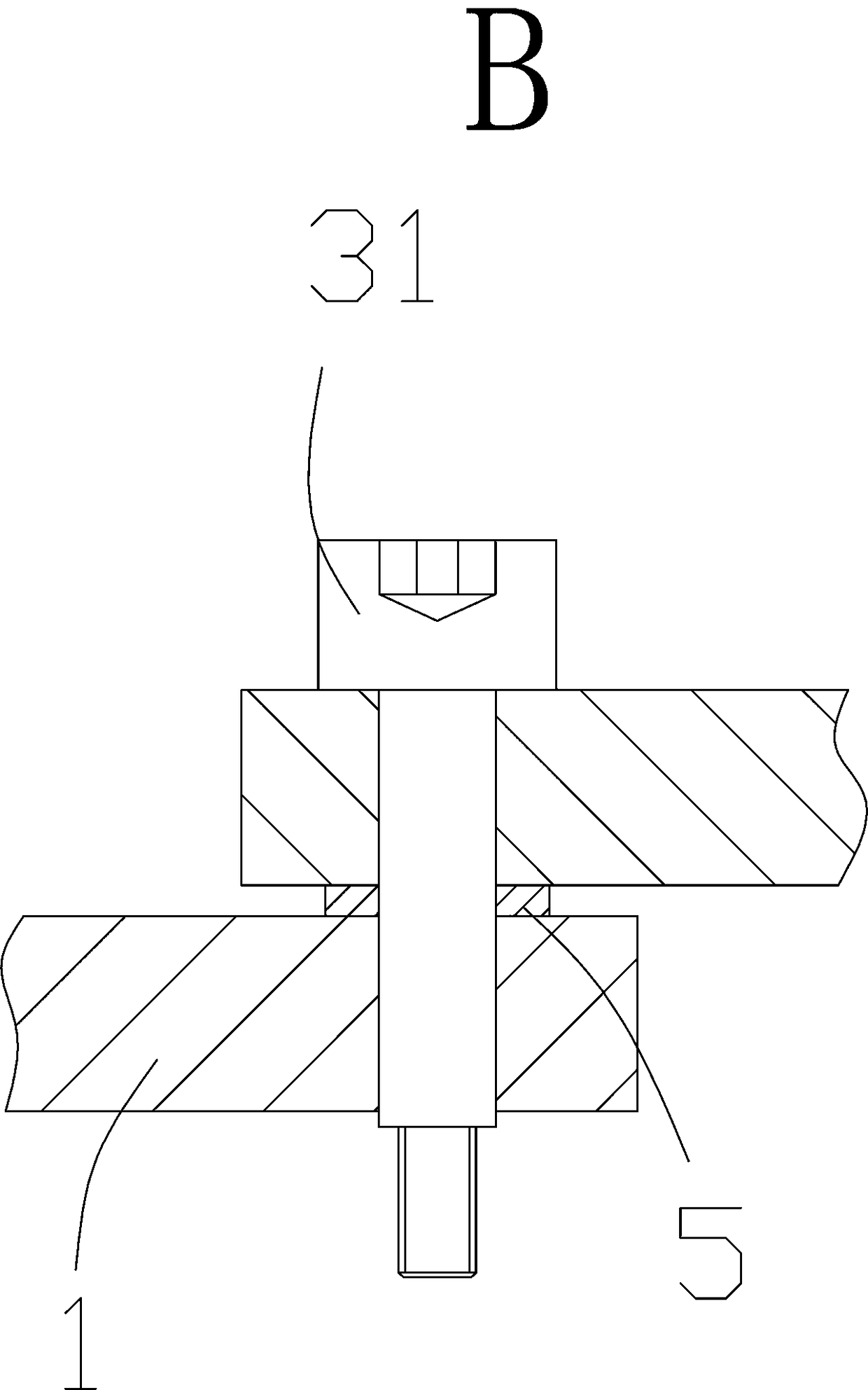
[0014] Such as Figure 1 to 5 As shown, an LED lamp lead frame with electroplating guide frame includes two sets of guide frames arranged oppositely in the electroplating tank (not shown in the figure of the electroplating tank), and the LED lamp lead frame tape 5 is clamped between the two sets of guide frames. The guide frame includes two supporting plates 1 whose corners are connected together by a first bolt shaft 31. The first bolt shaft 31 is screwed in the electroplating tank. The two supporting plates 1 are away from one end of the first bolt shaft 31. Connected by an elastic mechanism 4, the elastic mechanism 4 can push the two supporting plates 1 to rotate inward around the first bolt shaft 31, and a guide mechanism is installed on each supporting plate 1, and the guide mechanism includes a threaded connection The second bolt shaft 32 on the support plate 1, and the guide wheel 2 mounted on the second bolt shaft 32, the guide wheel 2 is composed of a cylindrical lower...


PUM


Abstract

The invention relates to an LED lamp lead wire frame strip electroplating guide frame, which comprises two sets of guide frames arranged oppositely in an electroplating groove, wherein an LED lamp lead wire frame strip is clamped between the two sets of the guide frames and horizontally moves, the guide frame comprises two support plates, one corners of the two support plates are connected by a first bolt shaft, the first bolt shaft is connected in the electroplating groove through threads, one ends, away from the first bolt shaft, of the two support plates are connected through an elastic mechanism, the elastic mechanism can push the two support plates to rotate inward around the first bolt shaft, each support plate is provided with a guide mechanism, the guide mechanism comprises a second bolt shaft connected on the support plate through threads, and a guide wheel arranged on the second bolt shaft, the guide wheel comprises a cylindrical lower part and a tapered upper part, a right-triangle cutting groove is formed between the upper part and the lower part, and the LED lamp lead wire frame strip is snapped in the cutting groove and horizontally moves.

Description

Technical field [0001] The invention relates to an LED lamp lead frame with electroplating guide frame. Background technique [0002] During the electroplating process of the LED light lead frame tape, it is necessary to position the LED light lead frame tape in continuous horizontal movement, so that the LED light lead frame tape is kept at a fixed height position for electroplating, so as to control the plating area. The guide method is to use two brass blocks with grooves. The edges of the LED light lead frame are clamped into the grooves of the two brass blocks to move horizontally. During electroplating, the LED light lead frame has brass on both sides. The block needs to be connected to the electrode to electroplate the LED light lead frame tape, but in actual operation, the distance between the two brass blocks is very difficult to adjust. If the distance is too wide, it will easily cause the LED light lead frame tape to be unable to be with the brass Good contact between...

Claims


Application Information

Patent Timeline
Patent Type & Authority Applications(China)
IPC IPC(8): C25D17/00C25D7/00
CPCC25D17/005C25D7/00
Inventor 徐百灵
Owner 徐百灵
Learn More